
Gear Shift Drive Components
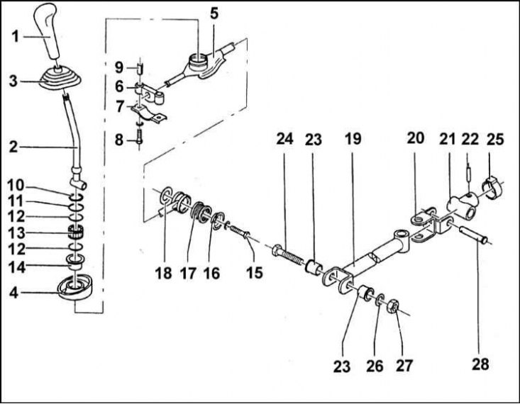
1 - Handle of the manual transmission control lever; 2 - Manual transmission control lever; 3 - External protective cover; 4 - Internal protective cover; 5 - Jet rod; 6 - Rubber stop; 7 - Mounting clamp; 8 - Bolt; 9 - Spacer sleeve; 10 - Retaining ring; 11 - Distance washer; 12 - Rubber rings; 13 - Bushings of the spherical hinge; 14 - Anther; 15 - Bolt M6; 16 - Washer; 17 - Rubber bushing; 18 - Washer; 19 - Gearshift drive rod; 20 - Cardan joint; 21 - Coupling; 22 - Pin; 23 - Plastic bushings; 24 - bolt; 25 - Traction clamp; 26 - Spring washer; 27 - Nut M8 (18 Nm); 28 - Pin
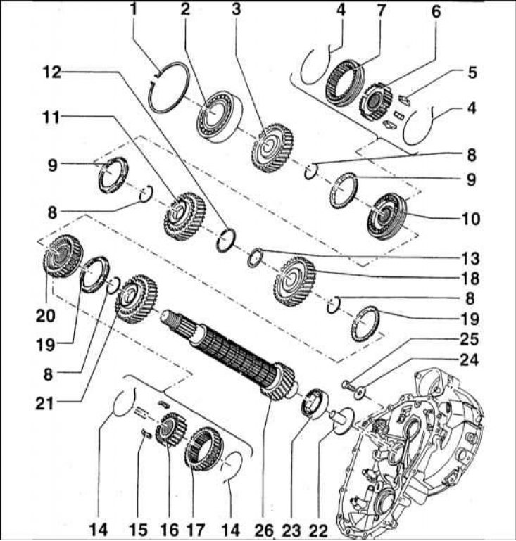
Assembly components of the 5th gear gear of the manual transmission
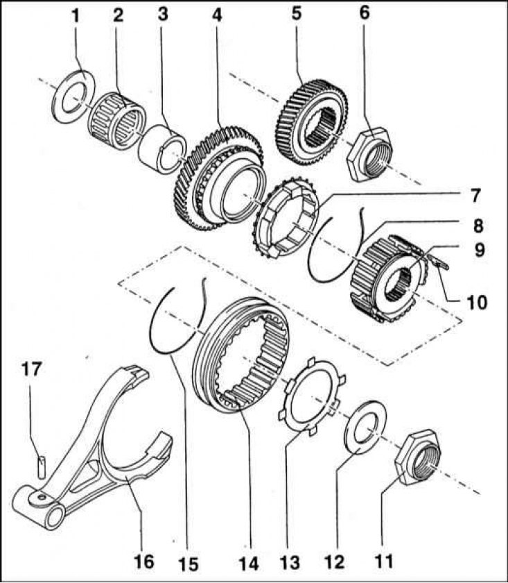
1 - Adjusting washer; 2 - Cage of the needle roller bearing of the gear of the 5th gear; 3 - Inner race of the bearing; 4 - Drive gear 5th gear; 5 - Driven gear of the 5th gear; 6 - Nut (60 Nm); 7 - Blocking ring of the synchronizer; 8 - Synchronizer spring; 9 - Hub of the sliding sleeve of the synchronizer; 10 - Sliding key synchronizer; 11 - Nut (60 Nm); 12 - Washer; 13 - Support ring; 14 - Sliding clutch of the synchronizer; 15 - Synchronizer spring; 16 - 5th gear engagement fork; 17 - Pin 5x22 (must be replaced without fail)
The procedure for installing the components of the assemblies of the primary and secondary shafts of the manual transmission
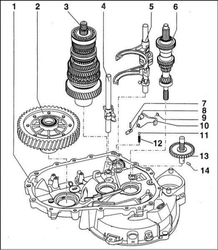
1 - Clutch dome; 2 - Assembling the main gear; 3 - Assembly of the secondary shaft; 4 - 5th gear fork rod; 5 - Rod forks of inclusion of 1/2 and 3/4 gears; 6 - Assembly of the input shaft; 7 - Pin 4x7; 8 - Pin of the reverse gear lever; 9 - Plug; 10 - Reversing lever; 11 - Retainer ball; 12 - Retaining spring; 13 - Intermediate reverse gear; 14 - Pin
Transmission input shaft
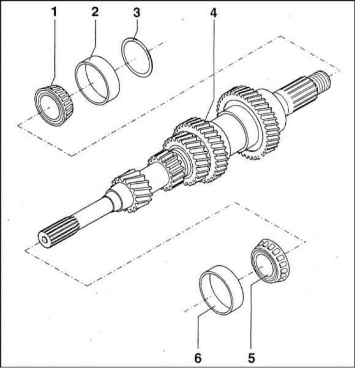
1 - Inner race of the tapered roller bearing; 2 - Outer race of tapered roller bearings; 3 - Distance washer; 4 - Primary shaft; 5 - Inner race of the tapered roller bearing; 6 - Outer race of tapered roller bearing
Components of the secondary shaft of the gearbox
1 - Retaining ring; 2 - Ball bearing; 3 - Gear 4th gear; 4 - Synchronizer spring; 5 - Sliding key of the synchronizer; 6 - Hub of the sliding sleeve of the synchronizer; 7 - Sliding clutch of the synchronizer; 8 - Retaining ring; 9 - Blocking ring of the synchronizer; 10 - Assembling the synchronizer 3/4 gears; 11 - Gear 3rd gear; 12 - Washer; 13 - Adjusting washer 2/3 gears; 14 - Synchronizer spring
Gearshift Components
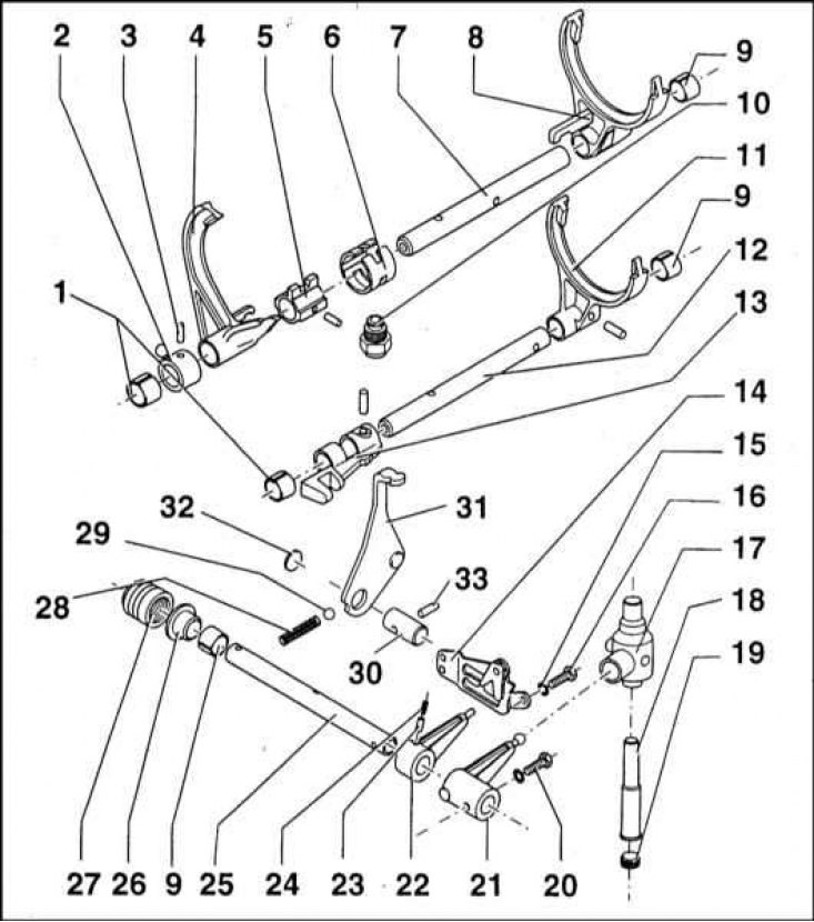
1 - Sleeve of a rod of a plug of inclusion of transfers; 2 - Coupling; 3 - Pin 5x22 (must be replaced during assembly); 4 - Fork of inclusion of 1/2 transfers; 5 - Spike gearshift mechanism; 6 - Retainer cracker; 7 - Rod of forks of inclusion of 1/2 and 3/4 gears; 8 - Fork of inclusion of 3/4 transfers; 9 - Rod sleeve; 10 - Locking bolt; 11 - 5th gear engagement fork; 12 - 5-1 gear fork rod; 13 - Spike of the mechanism for switching 5th and reverse gears; 14 - Guide link; 15 - Gasket; 16 - Bolt (10 Nm); 17 - Three-arm lever; 18 - Three-arm lever pin; 19 - Screw plug with hexagon socket (30 Nm); 20 - Bolt (17 Nm, lubricate with Loctite before installation); 21 - Executive lever of the gear selection rod; 22 - Finger backstage; 23 - Pin with spring; 24 - Pin with spring; 25 - Gear selection rod; 26 - O-ring of the selection rod; 27 - Anther; 28 - Retaining spring; 29 - Retainer ball; 30 - Finger of the reverse gear lever; 31 - Reverse gear lever; 32 - Plug; 33 - Pin 4x25
Overhaul - general information
The overhaul of the manual transmission requires a high level of qualification from the performer, as it involves the precise setting of many gaps by selecting shims and spacer bushings. In addition, the internal components of the gearbox are quite difficult to find on the open market, not to mention the high prices for them. In view of the foregoing, the compilers of this Guide recommend, in the event of problems in the operation of the manual transmission, to replace it with a new or refurbished unit.
However, a fairly experienced amateur mechanic can easily repair the gearbox on their own, provided that they have a special tool. Remember that all procedures must be performed strictly in the proper order. Do not rush, do not fuss, try not to miss any little things.
Among the special tools, without the use of which the repair of the manual transmission becomes impossible, are tongs for extracting the outer and inner circlips, a set of pullers, a sliding hammer, a set of drifts, a plunger-type dial gauge and, if possible, a hydraulic press. In addition, the workplace should be equipped with a large, sturdy workbench with a vise.
During the disassembly of the gearbox, the installation position of all removed components should be carefully recorded on paper in order to ensure that they are correctly positioned during assembly.
Before proceeding with the disassembly of the manual transmission, you should try to determine for yourself the possible causes of the violations that occur. Some problems are quite clearly tied to specific gearbox components, which can significantly reduce the time to identify and eliminate defects.
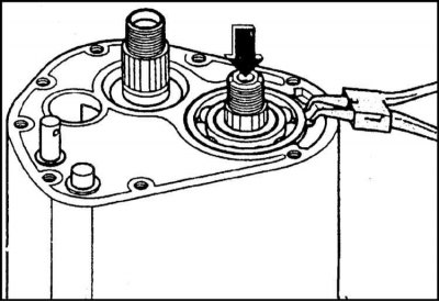
Disassembly and assembly of the manual transmission control lever
1. Components of the gearshift drive assembly are shown in the illustration. All references below correspond to the numbering adopted in this illustration (unless otherwise specified separately).
2. Remove the control lever handle (1).
3. Release from the center console panel and remove the outer protective cover from the lever (3).
4. Loosen the fixing nut and remove the bolt (15) fastening the control lever to the gearshift drive rod.
5. Loosen the torque arm fixing fastener (5) lever on the body and crankcase of the manual transmission.
6. Remove the lower arm guard (4).
7. Lower down and remove from the car assemblage of a jet bar with the control lever.
8. Remove retaining ring (10) and spacer (11).
9. Using a suitable pointed tool, pry out of the groove in the upper spherical joint bushing (13) edges of the rubber seal (12) and cut it with a knife. Then use pliers and remove the cut ring from the groove.
10. Using a screwdriver, remove the rubber boot from below (14).
11. Remove the bottom rubber o-ring of the spigot assembly.
12. From below, press the control arm assembly with pivot bushings out of the torque arm.
13. Assembly is carried out in the reverse order.
Removing the manual transmission crankcase cover, dismantling the support
Note. Lid removal can also be done in situ (directly on the car).
1. Fix the manual transmission assembly on the mounting stand.
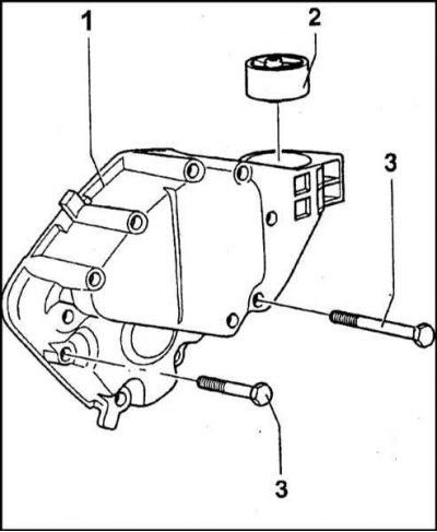
1 - Cover; 2 - Rubber-metal bushing of the power unit support; 3 - Cover bolts (25 Nm)
2. The cover is removed as an assembly with the power unit support. Loosen and remove the fixing bolts diagonally.
3. Remove the cover assembly with the power unit support from the gearbox housing.
4. Remove the front and rear mounting brackets of the powertrain support assembly.
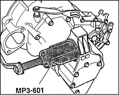
5. Using the tool MP 3-601, squeeze out the rubber-metal bushing of the manual transmission crankcase cover support.
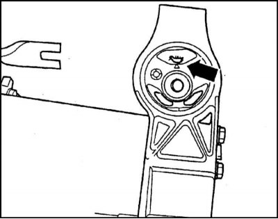
6. When installing, the rubber-to-metal support should be deployed as shown in the illustration.
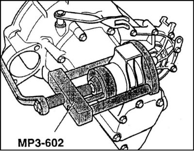
7. The bushing is pressed in using the MP 3-602 tool.
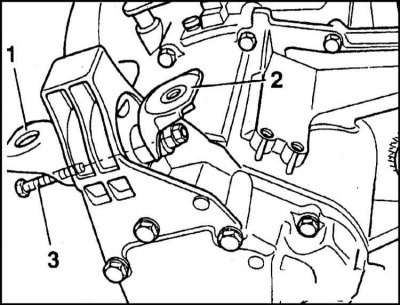
1 - Front mounting bracket support; 2 - Rear mounting bracket support; 3 - Fixing bolt (50 Nm)
8. Install the front pole mounting bracket (without weld nuts) from the starter side, and the rear (with welded nuts) - from the opposite side. Tighten the mounting bolt until the mounting brackets are in the up position and cannot rotate. The final tightening of the bolt is carried out after the gearbox / power unit has been mounted on the vehicle.
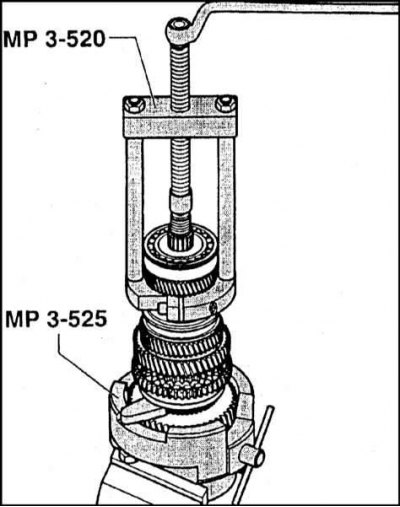
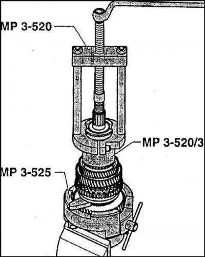
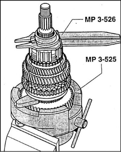
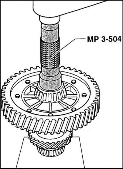
Dismantling and installation of the 5th gear assembly
Note. Dismantling of the 5th gear can be done without removing the box from the vehicle. In this case, it is necessary to block the unit using the device MP 9-502/1.
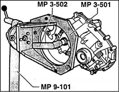
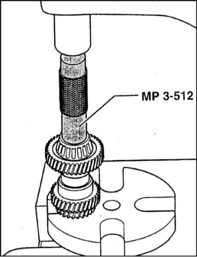
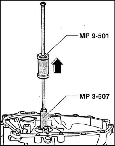
1. Block the manual transmission input shaft from turning using MP 3-502. If the box is not removed from the car, the shaft is blocked by turning on 4th gear.
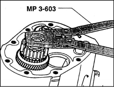
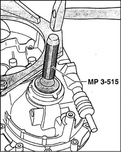
2. Loosen the driven gear mounting nut using tool MP 3-603.
Note. During assembly, the nut must be replaced without fail.
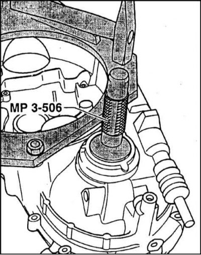
3. In the same manner, loosen the 5th gear drive nut on the input shaft.
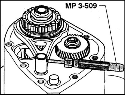
4. Knock out the mounting pin...
... and remove the 5th engagement fork together with the synchronizer sliding sleeve. Take care not to drop the sliding keys by immediately removing them from their slots in the hub.
5. Sequentially remove the 5th gear assembly components from both shafts.
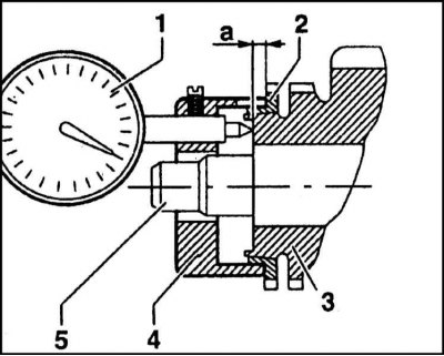
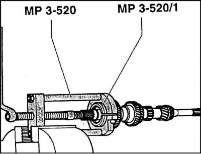
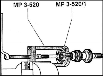
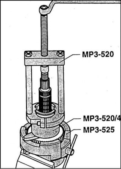
1 - Dial gauge; 2 - Synchronizer ring; 3 - Drive gear; 4 - Tool MP 3-535; 5 - Shaft
6. Installation is carried out in the reverse order. When mounting the synchronizer, the accuracy of the size setting of the sliding sleeve hub is of particular importance. The controlled parameter is the dimension a, which determines the distance from the end of the drive gear to the bearing surface of the synchronizer blocking ring. The measurement is carried out using a plunger-type dial gauge, to fix which on the assembly, MP 3-535 is used. Synchronizers are produced in three size groups:
- a = 2.75÷3.10 (mm)
- a = 3.11÷3.44 (mm)
- a = 3.45÷3.78 (mm)
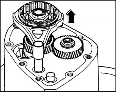
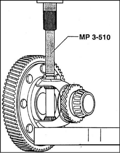
Dismantling and installation of the primary / secondary shafts of the manual transmission and final drive assembly
1. The order of installation of components of primary and secondary shafts in a transmission is shown on an illustration.
2. Remove the 5th gear reduction assembly.
3. Open and remove the ball bearing circlip. Pull the shaft all the way inside the clutch housing.
4. Remove the lock screw.
5. Turn out bolts of fastening of a dome of coupling to a manual transmission case.

6. Using the MP 3-503 tool, separate the clutch dome from the gearbox housing and put it aside.
7. By shifting the sliding sleeve of the synchronizer assembly with the inclusion fork, select 4th gear.
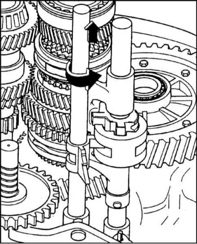
8. Rotate the 5th shift fork and reverse gear lever shaft approximately 15°counterclockwise and remove it from the assembly.
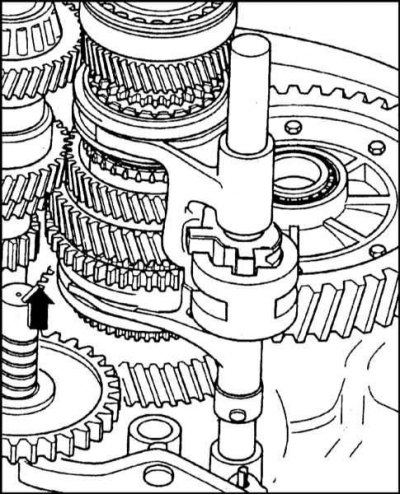
9. Remove the reverse idler gear assembly with its axle.
10. By shifting the sliding sleeves of the synchronizers, together with the inclusion forks, select 2nd and 4th gears.
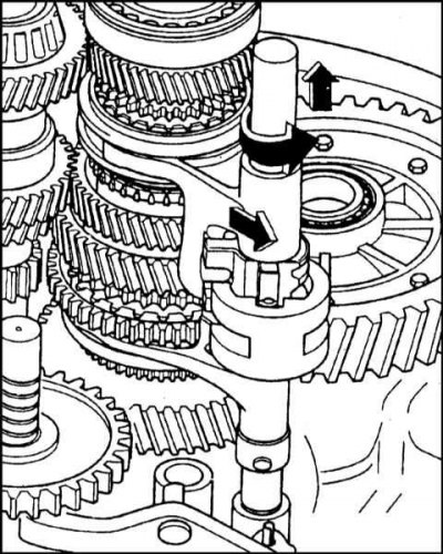
11. Remove remaining stem assembly with shift forks.
12. Remove the input shaft and final drive assembly from the gearbox housing.
13. Assembly is carried out in the reverse order.
Disassembly and assembly of manual transmission shafts
Input shaft
1. The installation order of the input shaft assembly components is shown in the illustration.
2. The procedure for dismantling the bearings is shown in the illustrations.
3. Installation is carried out in the reverse order.
Output shaft
1. The order of installation of the components of the output shaft assembly is shown in the illustration.
2. The procedure for dismantling the output shaft bearings is shown in the illustrations.
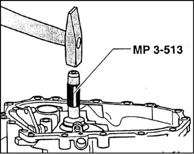
3. Assembly is carried out in the reverse order. The pinion shaft roller bearing is pressed in using MP 3-513 tool. Used blocking rings of synchronizers must be installed on the shaft strictly in their original places. Before installation, the blocking rings and bearings should be liberally lubricated with gear oil. Before proceeding with the assembly of the driven gears of the 1st ÷ 4th gears, it is also necessary to lubricate their sliding surfaces with a generous amount of oil. Try not to confuse the sliding keys of the 1/2 and 3/4 gear synchronizers during installation - they are not interchangeable.
Adjustment of backlashes in bearings of a primary shaft and differential
Note. Bearings and their seating surfaces must be thoroughly cleaned and degreased before installation.
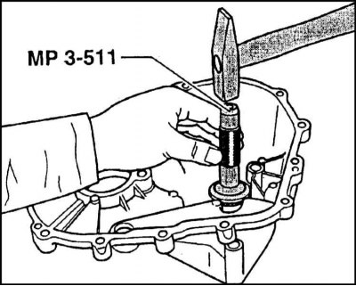
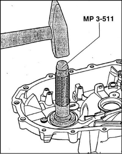
1. Using tool MP 3-511, press the outer race of the tapered roller bearing into the clutch housing until it stops.
2. Fill the MP 3-503/2 tool into the hole for installing the input shaft in the clutch housing and put on it the outer race of the smaller bearing of the input shaft tapered roller bearing.
3. Insert the final drive assembly into the clutch housing with the inner bearing races pressed into it.
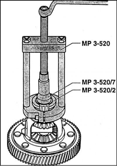
4. Put the outer race of the differential tapered roller bearing on the inner race and on the outer race of the MP 3-530/1 tool.
5. Screw the fastening nuts of the devices MP 3-530/1 and MP 3-530/2 up to the stop (leaving no gap).
6. Using the MP 3-511 tool, press the outer race of the tapered roller bearing with a larger diameter of the input shaft until it stops into the manual transmission housing.
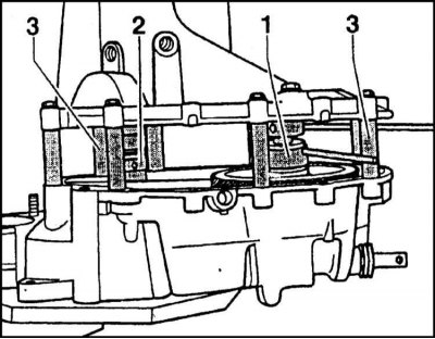
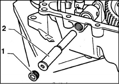
7. Install shouldered spacers on the clutch housing flange. Spacers should be installed on opposite sides in a diagonal pattern.
8. Place the crankcase on the spacers and secure it with bolts and washers supplied with the tool.
9. After inserting the remaining spacers, also secure them with screws and washers.
10. Gradually tightening the screws in a diagonal order, tighten them with a force of 25 Nm, thereby fixing the manual transmission housing and the MP 3-530 fixture.
11. Unscrew the adjusting nut of the MP 3-530/1 and MP 3-530/2 devices so that the bearings of the differential and the input shaft turn with slight resistance (without axial play).
12. Using blade-type feelers inserted into the gaps of the adjusting nuts, determine the dimensions of the required shims for both the final drive and the input shaft. Shims are available in the following thicknesses:
- Differential: 2.0÷2.7 mm in 0.1 mm increments
- Input shaft: 0.20mm, 0.25mm, 0.30mm, 0.36mm, 0.60mm and 0.80mm
13. After separating the manual transmission housing from the clutch dome, remove the tools.
14. In the hole for installing the differential bearing in the gearbox housing, install the required number of shims, achieving an installation dimension of +0.20 mm.
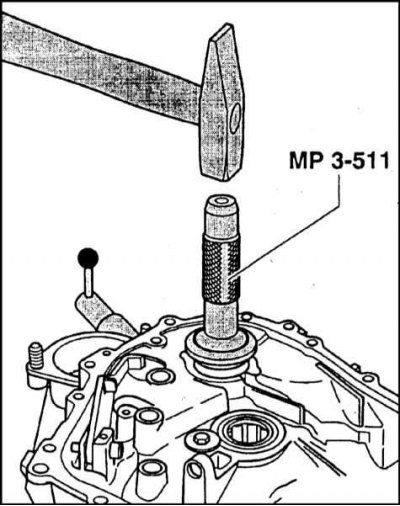
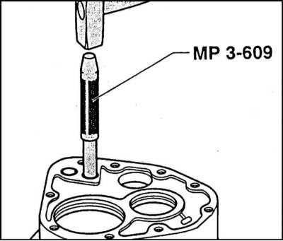
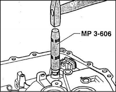
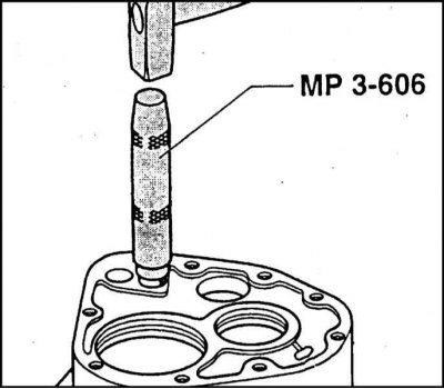
15. Using MP 3-511, seat the outer race of the tapered roller bearing of the differential all the way into the gearbox housing.
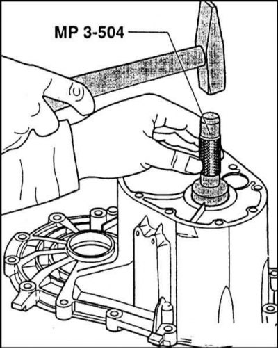
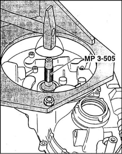
16. Using tool MP 3-505, push the outer race of the tapered roller bearing with a larger diameter of the input shaft from the gearbox housing.
17. Insert shims according to the set size into the opening of the gearbox housing for the fit of the tapered roller bearing of a larger diameter of the input shaft.
18. Using the MP 3-531 tool, press the outer race of the bearing with a larger diameter of the input shaft until it stops in the gearbox housing.
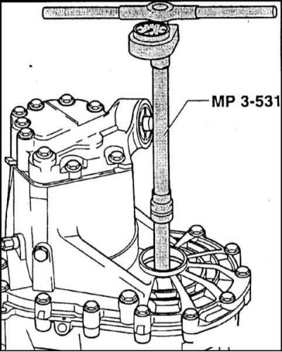
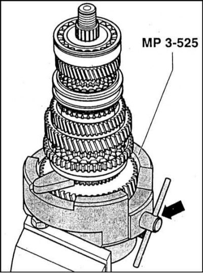
19. Check differential bearing preload using MP 3-531 tool and torque wrench.
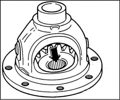
Disassembly and assembly of the differential
Disassembly and assembly of the differential is carried out using special tools.
Disassembly and assembly of the gear shift mechanism
1. The installation order of the components of the shift mechanism is shown in the illustration.
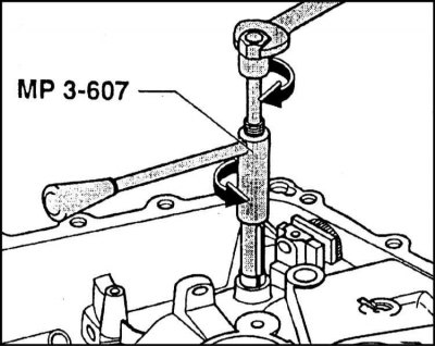
2. Disassembly and assembly of the gear shift mechanism is carried out using special tools.
3. Assembly is carried out in the reverse order.
Adjustment of the three-arm gearshift lever
Note. The indentation of the hole in the engagement fork rod for fixing the actuating lever must point upwards. The end of the yoke pin must not come into contact with the yoke when the shift fork stem is moved (achieved by the position of the actuating lever)
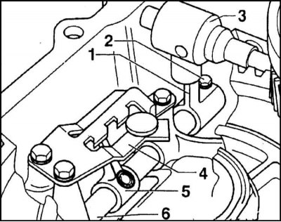
1 - Executive lever of the gear selection rod; 2 - Bolt; 3 - Three-arm lever; 4 - Guide link; 5 - Finger backstage; 6 - A rod of a fork of inclusion
1. Loosely screw in the bolt (2), pre-lubricated with Loctite type sealant.
2. Adjust the position of the end of the yoke pin so that it does not come into contact with the yoke when the yoke stem is moved.
3. Tighten the bolt (2) with a force of 14 Nm.
4. During assembly, the backstage finger must be replaced if the bore for the pin with the spring is squeezed out.