



Gearbox - appearance
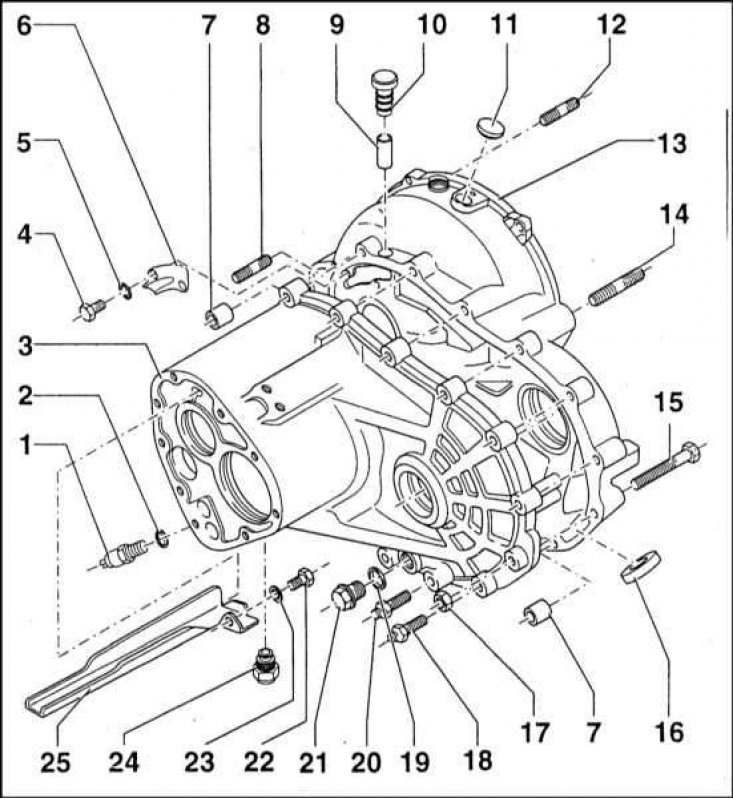
1 - Reverse light switch sensor; 2 - Sealing ring; 3 - Gearbox housing; 4 - Screw (10 Nm); 5 - Lock washer; 6 - Visor; 7 - Guide pin; 8 - Stud M10 (50 Nm); 9 - Ventilation tube; 10 - Cork; 11 - Plug; 12 - Stud (50 Nm); 13 - Clutch housing (dome); 14 - Stud (50 Nm); 15 - Screw; 16 - Magnet; 17 - Nut (35 Nm); 18 - Screw (25 Nm); 19 - Sealing ring (must be replaced during assembly); 20 - Drain plug thread (60 Nm); 21 - Screw (10 Nm); 22 - Thrust ring; 23 - Locking screw (35 Nm); 24 - Cork; 25 - Oil trough
The transmission assembly is housed in a cast aluminum crankcase bolted to the left end of the engine. The assembly includes the gearbox mechanisms as well as the main gear differential.
Rotation is transmitted from the engine crankshaft through the clutch assembly to the primary shaft of the manual transmission, equipped with an extended and splined journal, which is threaded into the hub of the friction disk of the clutch. The primary shaft of the box rotates in non-separable ball bearings placed in a sealed housing. From the primary shaft, rotation is transmitted to the secondary shaft of the box, the right end of which is threaded into a roller bearing, and the left - into a sealed ball bearing. The output end of the secondary shaft of the box is engaged with the crown driven gear of the main transmission, rigidly connected to the differential box, inside which there is a planetary assembly. From the side gears of the differential, rotation is transmitted further to the drive shafts and then to the leading front wheels of the car. The satellite gears are freely mounted on their axis, which allows the vehicle's drive wheels to rotate at different speeds, thereby completely eliminating the possibility of the inner wheel slipping during maneuvers.
The primary and secondary shafts of the gearbox are located parallel to each other, as well as parallel to the crankshaft and drive shafts of the drive axle. Due to the configuration, the gears of both shafts are constantly in engagement with each other. In neutral gear, the gears rotate freely on the secondary shaft, without transmitting rotation to the driven gear of the main gear.
Gear shifting is performed using the manual transmission control lever installed on the floor of the passenger compartment and by means of the gear selection drive mechanism. The gear selection drive mechanism consists of a set of shift forks, with the help of which the sliding synchronizer clutches move along the shaft, locking the gears of the corresponding gears with their hubs. Since the hubs of the sliding clutches are equipped with splines engaged with the mating splines of the secondary shaft, the gear locked on the hub begins to rotate together with the shaft, providing further drive with the corresponding gear ratio. To ensure the speed and quality of gear shifting, the gearbox provides synchronization of all forward gears. Synchronization is ensured by using locking rings with spring-loaded sliding keys and synchronizer hubs with gears. The synchronizer cones provide mating surfaces for the locking rings with gears. The design and operation principle of the manual transmission are described in more detail in Section System design, description of individual units and mechanisms.