
Removing
Note. Reassembly will require new mounting bolt nuts as well as new circlips for the driveshaft inner pivots.
1. Support the rear wheels of the vehicle. Apply the parking brake, then jack up the front of the vehicle and place it on jack stands. Remove both front wheels.
2. If equipped, unscrew the fixing screws and remove the crankcase protection.
3. Drain gear oil. After replacing the sealing washer, screw the drain plug back into place and tighten it with the required force.
4. On 1.3 l models, remove the Hall sensor from the gearbox. On models with central fuel injection, also remove the air cleaner cover from the throttle body.
5. On all models, remove the starter.
6. Loosen the knurled nut and disconnect the drive cable from the speedometer drive mechanism at the rear of the manual transmission (see Section Removal and installation of the speedometer drive mechanism).
7. Loosen the clutch cable adjusting nut, loosening the latter as much as possible. Disconnect the cable from the clutch release lever and release it from the support bracket. Pull the cable away from the gearbox. Disconnect the spring and remove it from the upper end of the pivot shaft of the clutch fork.
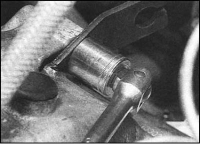
8. Remove the clamp installed on the transmission side of the selector rod to provide access to the mounting roll pin.
Note. During assembly, it would be more correct to replace the standard factory-fitted clamp with a more practical screw or worm. Using a punch and hammer, knock out the pin and disconnect the stem from the axle of the shift forks. Discard the old pin - it must be replaced during assembly.
9. Turn out a bolt of fastening of a bar of the mechanism of switching to a transmission. Disconnect the rod and remove the washers.
10. Disconnect the electrical wiring from the sensor-switch of the reversing lights (one or two sockets).
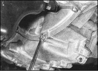
11. Give fixing bolts...
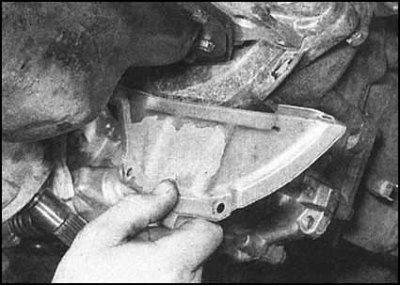
...and remove the bottom flywheel cover plate from the base of the clutch dome.
12. Release the inner end of the left drive shaft from the differentiahpout giving the shaft fastening nut on the hub, tie it with wire to the suspension elements.
13. With the shaft free, insert a piece of metal bar or pipe with a diameter of about 26 mm into the shaft seat and push it through the hole in the differential side gear, leaving the end protruding from the crankcase. If necessary, secure the rod to the outside of the gearbox housing with adhesive tape.
Attention! If you do not take care of fixing one of the side gears in the event of the simultaneous dismantling of both drive shafts, both gears may fall inside the differential box and to remove them, you will have to produce a manual transmission and deliver it to a car service workshop.
14. Having securely fixed the left side gear of the differential, disconnect the right drive shaft from the box. Tie the shaft with wire to the suspension elements.
15. Support the engine with a jack (to distribute the load between the head of the jack and the sump, lay a block of wood). Alternatively, the power unit can be hung from above using a winch or beam (lifting eyes must first be installed on the engine). Jack up the gearbox too (don't forget the bar).
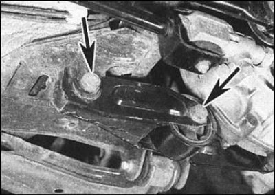
16. Loosen the nuts and bolts securing the cheeks of the rear support of the power unit to the gearbox housing and the car body. Remove the support cheek. Nuts can be thrown away - during assembly they must be replaced without fail.
17. Give a nut of a forward bolt of a fixing plate of the left support, then turn out both bolts and remove a plate. The nut must be replaced without fail.
18. Take the weight of the gearbox on the jack, then give the remaining nuts and bolts securing the gearbox housing to the engine. Try to remember the installation position of each of the fastener elements, as well as the brackets and brackets fixed by them along the way. Make sure one last time that nothing is left connected to the box to prevent it from being removed.
19. Slightly lower the gearbox and begin to move it to the left, removing it from the guide pins. after separating the box from the engine, lower the jack and remove the assembly from under the car. Remove the loose-fitting guide pins and stow them in a safe place.
Installation
1. Lightly lubricate the contact surfaces of the release bearing, release fork, and bearing guide with high temperature grease such as Kluber Microlube GL202, GL261, or GL262, or Mobil lithium 932 or 933. Be careful not to get grease on the friction linings. Remove excess grease. Check the clutch release mechanism for proper operation. Lightly lubricate the input shaft stub splines as well.
2. Check that the guide pins fit correctly in their sockets. Raise the gearbox to its original position and press it against the engine. Screw in the mounting bolts / nuts - do not forget about the installation of mounting brackets and brackets fixed with the same fasteners. Lightly tighten the fastener.
3. Raise the manual transmission assembly until the components of the left support are aligned.
4. Establish a plate of the left support, screw fixing bolts and tighten them with the demanded effort. Screw a new fixing nut onto the front bolt and tighten it also with the required force.
5. Reinstall the cheek of the rear support of the power unit, insert the bolts and screw on the new nuts. Remove the jacks from under the box and engine. Shake the assembly of the power unit, for its final shrinkage, then tighten the nuts of the rear support bolts with the required force.
6. Further assembly is carried out in the reverse order of dismantling. Pay attention to the following points:
- a) Tighten all fasteners with the required force;
- b) Don't forget to replace the driveshaft seals (see Section Replacement of oil seals).Install the right shaft first, then the left;
- c) Use a new roll pin to secure the selector rod to the shift fork shaft. The pin should be fixed with a screw or worm type clamp;
- d) Before installing the shift rod bolt to the gearbox, carefully clean its threads, then lubricate with fresh locking sealant such as Loctite 270 or Three bond 1305. Lubricate all other bolts with the same sealant;
- e) After connecting the clutch cable, adjust it (see Section Removal, installation and adjustment of the clutch cable);
- f) Finally, fill the gearbox with the required amount of gear oil of the required grade and check its level.