



Contents: Carter ⬇ Primary shaft ⬇ Secondary shaft ⬇ Gears of transmission ⬇ Lubrication system ⬇ Main gear ⬇ Gear shift mechanism ⬇ Gear shift drive ⬇
Section of the manual transmission
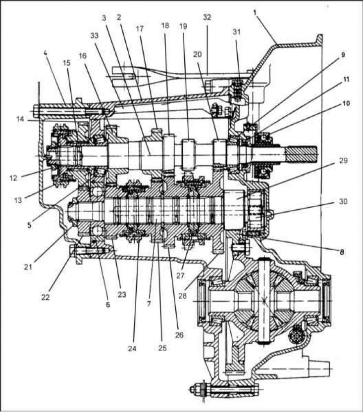
1 - Clutch housing (dome); 2 - Gearbox housing; 3 - Primary shaft; 4 - Lid; 5 - Bearing 30205; 6 - PLC Bearing 05-12; 7 - Secondary shaft; 8 - Driven gear of the main transmission; 9 - Bearing 32005; 10 - Clutch release bearing; 11 - Primary shaft seal; 12 - Nut M22; 13 - 5th gear synchronizer; 14 - 5th gear pinion; 15 - Bearing of 5th gear pinion PLC 43-18; 16 - 4th gear pinion; 17 - 3rd gear pinion; 18 - 2nd gear pinion; 19 - Reverse gear; 20 - 1st gear pinion; 21 - Nut M22; 22 - 5th gear pinion; 23 - 4th gear pinion; 24 - Synchronizer 3/4 gears; 25 - 3rd gear pinion; 26 - 2nd gear pinion; 27 - Synchronizer 1/2 gears; 28 - 1st gear pinion; 29 - Main gear pinion; 30 - PLC Bearing 44-17; 31 - Ventilation plug; 32 - Clutch release lever; 33 - Oil drain
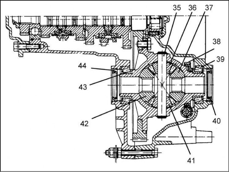
35 - Differential satellite axle; 36 - Satellite; 37 - Right drive shaft side gear; 38 - Speedometer drive gear; 39 - PLC 64-7 bearing; 40 - Seal; 41 - Satellite; 42 - Left drive shaft side gear; 43 - PLC 64-7 bearing; 44 - Seal
Main gear assembly components
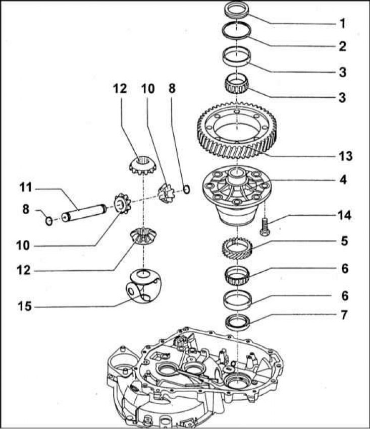
1 - Seal; 2 - Adjusting washer; 3 - PLC 64-7 bearing; 4 - Differential box; 5 - Speedometer drive gear; 6 - PLC 64-7 bearing; 7 - Seal; 8 - Retaining ring; 10 - Satellite; 11 - Axle of satellites; 12 - Bevel side gears; 13 - Driven gear of the main transmission; 14 - Screw (8 Nm); 15 - Plastic ball insert
Gear shift mechanism
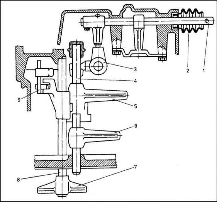
1 - Gear selection rod; 2 - Protective case; 3 - Three-arm gear selector lever; 4 - 1/2 and 3/4 gear engagement fork rod; 5 - 1/2 gear engagement fork; 6 - 3/4 gear engagement fork; 7 - 5th gear engagement fork; 8 - 5th gear shift fork rod; 9 - Reverse gear lever
Gear shift mechanism drive hinge assembly
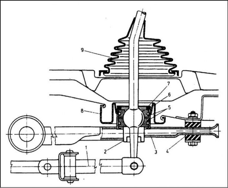
1 - Cardan joint; 2 - Dust cover; 3 - Reactive rod; 4 - Rubber stop; 5 - Rubber rings; 6 - Distance washer; 7 - Retaining ring; 8 - Inner protective casing; 9 - Outer protective casing
Carter
The cross-section of the gearbox is shown in the illustration.
The cast aluminum gearbox housing consists of three interconnected parts: the clutch housing (dome) and the main gear, the manual transmission housing itself, and the cover. On the outside of the cover, there is a flange for installing the power unit support. The cover is attached to the gearbox housing with six long M8x80 bolts and three short M8x35 bolts.
In the lower part of the manual transmission housing there is a hole into which the reverse light switch sensor is screwed. The drain plug has an M22 thread, its sealing is ensured by an aluminum sealing washer with an external diameter of 27 mm and an internal diameter of 22 mm.
A magnet is fixed inside the crankcase, designed to remove metal particles from the transmission oil that are formed during the operation of the internal components of the manual transmission.
Primary shaft
The primary shaft is installed in the manual transmission housing on two tapered roller bearings: type 30205 AC6 and type 32005 AC6.
The shaft is supplied assembled with helical gears of 1÷4 gears and a straight gear of the reverse gear. In this case, the gears of the 1st, 2nd and reverse gears are one piece with the shaft, and the 3rd and 4th are pressed on. The gear of the 5th gear is mounted on the shaft on a needle bearing of the PLC 43-18 type.
In front of the 5th gear pinion there is its synchronizer, then the M22x1.5 nut (12) is screwed on.
Secondary shaft
The secondary shaft is made integral with the main gear pinion and is installed in the manual transmission on two bearings: a single-row ball bearing of the PLC 05-12 type and a special bearing of the PLC 44-17 type. Between the first bearing and the main gear pinion there are the 4th gear pinions, the 3/4 gear synchronizer, the 3rd gear pinion, then the 2nd, then the 1/2 gear synchronizer, and finally the 1st gear pinion. In front of the ball bearing there is the 5th gear pinion, secured with an M22x1.5 nut. The 1/2 gear synchronizer clutch is equipped with a toothed rim designed to engage reverse gear.
Helical gears of 1÷4 gears are equipped with additional toothed rims for coupling them with synchronizers.
Gears of transmission
All the listed gears of both shafts are in constant engagement with each other. When the engine is running and the neutral gear is engaged, the gears of the secondary shaft rotate freely on it (the exception is the 5th gear), the shaft itself remains stationary. At the same time, when the clutch is engaged, the gears of the primary shaft rotate with it, with the exception of the 5th gear gear, which, while turning, remains stationary.
The use of helical gears in the gearbox has made it possible to significantly reduce the noise level.
Synchronizers ensure that the shaft is engaged with the gear corresponding to the selected gear without impact, only after their rotation frequencies have been equalized, which guarantees smooth shifting.
The intermediate gear is designed to connect the reverse gears of the primary and secondary shafts. When the reverse gear is disengaged, the shaft gears are disengaged (unlike gears of other transmissions). When the reverse gear is engaged, the intermediate gear simultaneously engages with the reverse gears of both shafts. This double engagement causes the secondary shaft to rotate in the same direction as the primary shaft, and the vehicle's drive wheels also begin to rotate in the opposite direction, ensuring the vehicle's forward movement in reverse. Since all the gears considered in this case are straight-toothed, a synchronizer is not provided here and the reverse gear should be engaged only after the vehicle has come to a complete stop.
Lubrication system
Lubrication is supplied to the internal components of the manual transmission by the driven gear of the main transmission, which is partially immersed in oil and carries it upwards when rotating. From above, the oil flows down the main system into the secondary shaft channel and lubricates the gears and synchronizers.
Inside the gearbox housing there is a small oil drain (33), through which the oil splashed by the gears is supplied to the bearing of the 5th gear gear.
There is a ventilation hole in the upper part of the crankcase, which is sealed with a plastic plug. The cylindrical part of the plug has turns that make it difficult for oil to pass through, but allow air to pass through freely.
Main gear
The components of the main transmission are shown in the illustration. The assembly is designed to transmit torque from the secondary shaft of the manual transmission to the drive shafts of the leading front wheels of the car, as well as to increase this torque.
The increase in torque is achieved through a constant gear ratio (see Specifications).
The main components of the reverse gear are: the drive gear, the teeth of which are cut directly on the body of the secondary shaft of the gearbox, the crown driven gear, to the end of which the differential box is attached with eight bolts. The main gear of this design is called cylindrical and differs from others in that it does not change the direction of torque transmission. The drive gear of the main gear has 19 teeth, the driven gear has 74.
The combination of the driven gear with the differential box made it possible to use the latter's housing as support journals for mounting the assembly in bearings.
The differential allows the vehicle's drive wheels to rotate at different speeds. When cornering, the inner wheel moves at a smaller radius than the outer wheel, and if the wheel speeds are the same, slippage will inevitably occur, leading to rapid wear of the wheels. A similar situation can occur when the vehicle is moving in a straight line, when the tires of the right and left drive wheels are worn to different degrees or inflated to different pressures. In order to prevent slippage and reduce the load on the transmission, each of the vehicle's drive wheels is driven by a separate shaft connected to the manual transmission via a differential mechanism.
The differential consists of a housing (box), satellites mounted on the axle and bevel side gears mated with the drive shafts of the vehicle's drive wheels. The differential housing is non-detachable. Cutouts are provided in it for installing internal components. In the horizontal plane, the differential housing ends with journals onto which PLC 64-7 type bearings are pressed. The outer bearing races, in turn, are pressed into the holes of the manual transmission housing.
The original article is available on www.SKODABOOK.ru
The bearings are installed without clearance. Preload is achieved by placing an adjusting washer of the appropriate thickness in the left bearing hole. Washers are available with a thickness of 2.0 to 2.7 mm in 0.1 mm increments. An additional gear is installed on the journal located closer to the flywheel, designed to drive the speedometer.
The holes for the drive shafts in the manual transmission housing are sealed using seals measuring 40x55x7 mm.
The satellite axle is made of a steel rod and is secured from falling out of the differential box by two retaining rings, which are pressed into specially provided grooves at both ends of the axle.
Satellites are bevel gears that rotate freely on their axis. Between the wide ends of the satellites and the walls of the differential box, disc washers are installed, which act as bushings.
The bevel side gears of the differential are in constant engagement with the satellites. On the walls of their holes, longitudinal splines are cut, which engage with the splines of the internal journals of the drive shafts.
In rectilinear motion (and the same wheel parameters) satellites, and the side gears that are in constant engagement with them remain stationary relative to their axis and housing. The differential is a kind of monolithic assembly, rotating both drive shafts at the same speed. When the car is moving along a curve, or with different characteristics of the wheel assemblies, one of the wheels (internal by turning radius, or larger diameter) encounters greater resistance, which is rigidly transmitted to the corresponding side gear of the differential, causing it to slow down due to the relative movement of the planetary assembly with the satellites starting to rotate. Despite the difference in the rotation frequency of the vehicle's drive wheels, the magnitude of the torque transmitted to them remains the same. Moreover, if one wheel hits a surface area with a reduced adhesion component (ice, snow, sand, etc.), and the second remains on a hard surface, then the first wheel will rotate at an increased (up to double) speed, while the second may stop rotating altogether.
During operation of the vehicle, it is necessary to ensure that the characteristics of the right and left driving wheels of the vehicle are identical (tire inflation pressure, tread wear, geometric characteristics, etc.), because otherwise the differential will continue to function even when driving in a straight line, creating additional resistance associated with increased fuel consumption.
Gear shift mechanism
The gear shift mechanism consists of a gear selector rod, two gear shift fork rods and a device that prevents two gears from being engaged simultaneously.
The gear selection rod is connected to the gear shift drive rod at one end, and a three-arm control lever for the gear shift rods is attached to its other end. The place where the gear selection rod exits the gearbox housing is protected from dust by a rubber cover.
On one of the shift rods are mounted the forks for engaging 1/2 and 3/4 gears. On the other - the fork for engaging 5th gear and the reverse gear lever.
The ends of the forks are placed in the grooves of the outer rings of the corresponding synchronizers. The movement of the fork leads to the displacement of the synchronizer and the engagement of the leading and driven gears of the corresponding transmission.
Gear shift drive
The reaction rod, located under the bottom of the body, is attached to the gearbox and the bottom. A bolt M6x20 is screwed into the gearbox, passing through a rubber bushing, seated in the tip of a specially shaped reaction rod. The rear end of the rod is installed in a rubber stop, pressed from below by a fastening clamp, pulled together by two bolts M8x40. Bushings are seated in the holes of the rubber stop, protecting the assembly from excessive compression. The control lever of the manual transmission is slightly curved and is equipped with a spherical joint at the bottom. The lower end of the lever ends in a transverse axial bushing, and the upper end is equipped with a handle.
The lever hinge is placed in a cavity formed by two specially shaped bushings seated in the support. On the outer surfaces of both bushings there are grooves in which rubber rings are seated. The entire assembly is fastened from above in the support using a locking ring, under which a spacer washer is seated. A rubber boot protects the assembly from contamination.
The cross bushing located at the lower end of the manual transmission control lever is designed to connect the lever to the fork of the gearshift mechanism drive rod using an M8 bolt and nut. The other end of the rod ends with a cross bushing, with the help of which it is connected to the cardan joint connecting the rod to the gear selection rod. At the end of the gear selection rod there is a connecting sleeve 8x20 mm, secured with a cylindrical pin.