



Contents: Assembly diagram of the activated…⬇ Removal ⬇
Assembly diagram of the activated carbon tank system
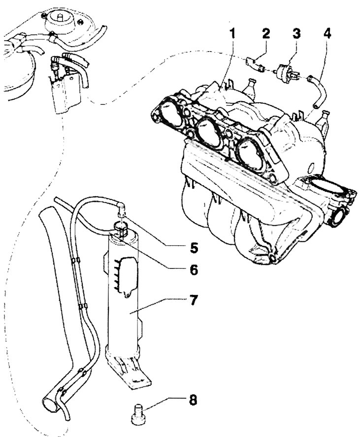
1 - Intake gas pipeline; 2 - Air bleed hose; 3 - Solenoid valve "N80", secured with a holder on the intake manifold, the valve is activated by clock pulses from the engine control unit; 4 - Air bleed hose; 5 - Ventilation line, from the solenoid valve "N80"; 6 - Vent line, from the gravity valve on the fuel tank; 7 - Activated carbon tank, assembly location: in the wheel arch of the right rear wheel, secured to the body, filled from the "N80" valve and from the gravity valve, checking the ventilation of the fuel tank; 8 - 10 Nm
Removal
Remove the right rear wheel. Remove the plastic wheel arch cover. Disconnect pipes "5" and "6". Remove screw "8". Pull the tank out downwards. It is carried out in the reverse order of actions.
(The original article is available on SKODABOOK)