



Fuel system (diesel, 1.9 l) of car Skoda Fabia 2
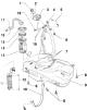
Fuel tank with installed parts
Fuel tank with installed parts 1 - Cork; 2 - Seal; 2 - Fuel tank filler neck, with rubber neck; 3 - Gravity valve, to remove, release the valve: the clamping clamps by pulling it upwards, check the valve's drainage...
Fuel tank with installed parts 1 - Cork; 2 - Seal; 2 - Fuel tank filler neck, with rubber neck; 3 - Gravity valve, to remove, release the valve: the clamping clamps by pulling it upwards, check the valve's drainage...

Removal and installation the fuel cooler
Important: The fuel cooler is located on the fuel return line leading to the fuel tank. It is located on the underside of the car body base. Remove the lower body cover. Disconnect the fuel line from the fuel cooler....
Important: The fuel cooler is located on the fuel return line leading to the fuel tank. It is located on the underside of the car body base. Remove the lower body cover. Disconnect the fuel line from the fuel cooler....

Removal and installation the fuel tank
Remove the fuel tank filler cap. Fold the right rear seat upright. Remove the fuel pump cover under the carpet. Disconnect the four-pin fuel pump connector. Empty the fuel tank. Remove the rear suspension. Remove the...
Remove the fuel tank filler cap. Fold the right rear seat upright. Remove the fuel pump cover under the carpet. Disconnect the four-pin fuel pump connector. Empty the fuel tank. Remove the rear suspension. Remove the...

Removal and installation the fuel pump
Important: If necessary, empty the fuel tank. Fold the right rear seat upright. Remove the fuel pump cover under the carpet. Disconnect the four-pin fuel pump connector "3". To release the fuel line, press the lower...
Important: If necessary, empty the fuel tank. Fold the right rear seat upright. Remove the fuel pump cover under the carpet. Disconnect the four-pin fuel pump connector "3". To release the fuel line, press the lower...

Removal and installation the fuel gauge sensor «G»
Remove the fuel pump. Important: When installing, ensure that the contact terminals of the arguments are positioned correctly. Release the retaining tabs of wiring connectors "3" and "4" and remove them. Using a...
Remove the fuel pump. Important: When installing, ensure that the contact terminals of the arguments are positioned correctly. Release the retaining tabs of wiring connectors "3" and "4" and remove them. Using a...

Removal and installation a turbocharger with installed parts
Engine with the letter designation BSW 1 - Intake gas pipeline; 2 - Inlet manifold, with mechanical EGR valve; 3 - Intake manifold flap motor "V157"; 4 - From the charge air cooler; 5 - Seal, replace; 6 - 25 Nm; 7 -...
Engine with the letter designation BSW 1 - Intake gas pipeline; 2 - Inlet manifold, with mechanical EGR valve; 3 - Intake manifold flap motor "V157"; 4 - From the charge air cooler; 5 - Seal, replace; 6 - 25 Nm; 7 -...

Removal and installation of intake air cooling components
Important: All hose connections are secured with clamps. The supercharging system must be sealed. Boost pressure hoses and charge air pipes, as well as their connections, must be free of oil and grease before...
Important: All hose connections are secured with clamps. The supercharging system must be sealed. Boost pressure hoses and charge air pipes, as well as their connections, must be free of oil and grease before...

Installation diagram of intake hoses
Engine with the letter designation BSW 1 - Valve block, the components of the valve block are: electromagnetic valve for exhaust gas recirculation -N18, magnetic valve for limiting the boost pressure "N75"; 2 -...
Engine with the letter designation BSW 1 - Valve block, the components of the valve block are: electromagnetic valve for exhaust gas recirculation -N18, magnetic valve for limiting the boost pressure "N75"; 2 -...

Removal and installation the charge air cooler
Remove the right front wheel arch (fender) liner. Remove the front bumper. For engines with the letter designation BSW Disconnect plug connector "1" from boost pressure sensor "G71" with intake air temperature sensor...
Remove the right front wheel arch (fender) liner. Remove the front bumper. For engines with the letter designation BSW Disconnect plug connector "1" from boost pressure sensor "G71" with intake air temperature sensor...
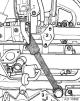
Removal and installation a turbocharger for an engine with the letter designation BLS
Remove the front section of the exhaust pipe with the particulate filter. Disconnect the G70 air flow meter connector. Remove the air intake hose from the turbocharger and air filter connection. Remove the connecting...
Remove the front section of the exhaust pipe with the particulate filter. Disconnect the G70 air flow meter connector. Remove the air intake hose from the turbocharger and air filter connection. Remove the connecting...

Fuel supply of a diesel engine
Assembly location diagram Engines with the letter designation BSW Parts marked with letters A through H are not shown on the assembly location diagram. A - Relay for direct fuel injection system of diesel engine "J322",...
Assembly location diagram Engines with the letter designation BSW Parts marked with letters A through H are not shown on the assembly location diagram. A - Relay for direct fuel injection system of diesel engine "J322",...

Removal and installation the intake manifold throttle valve
Engine with the letter designation BSW After the engine is turned off, the throttle valve in the intake manifold closes for about 3 seconds and then opens again. This reduces the shock when turning off. 1 - Intake gas...
Engine with the letter designation BSW After the engine is turned off, the throttle valve in the intake manifold closes for about 3 seconds and then opens again. This reduces the shock when turning off. 1 - Intake gas...

Disassembling and assembling the air filter
Engine with the letter designation BSW 1 - Air hose to the intake manifold, observing the correct position for assembly; 2 - Spring clamp; 3 - Upper air filter housing; 4 -2 Nm; 5 - Filter element; 6 - 8 Nm; 7 - Lower...
Engine with the letter designation BSW 1 - Air hose to the intake manifold, observing the correct position for assembly; 2 - Spring clamp; 3 - Upper air filter housing; 4 -2 Nm; 5 - Filter element; 6 - 8 Nm; 7 - Lower...

Removal and installation the air filter
After releasing the spring clamp "1" on the air hose, remove the hose from the air filter. After removing the air bleed hose "2", disconnect the plug connector on the air flow meter "3". Remove the air line "4" from the...
After releasing the spring clamp "1" on the air hose, remove the hose from the air filter. After removing the air bleed hose "2", disconnect the plug connector on the air flow meter "3". Remove the air line "4" from the...

Repair of pump-injector units
Always replace O-rings and sealing rings. 1 - 20 Nm + turn an additional 1/4 turn (90°), replace; 2 - Rocker arm support, with rocker arms; 3 - Lock nut, 30 Nm; 4 - Set screw, when installing a new pump-injector unit...
Always replace O-rings and sealing rings. 1 - 20 Nm + turn an additional 1/4 turn (90°), replace; 2 - Rocker arm support, with rocker arms; 3 - Lock nut, 30 Nm; 4 - Set screw, when installing a new pump-injector unit...

Engine control unit
Removal and installation the engine control unit "J623" Important: If the engine control unit is to be replaced correctly, the VAS 5051 must be connected and the "Replace Engine Control Unit" function must be performed....
Removal and installation the engine control unit "J623" Important: If the engine control unit is to be replaced correctly, the VAS 5051 must be connected and the "Replace Engine Control Unit" function must be performed....

Removal and installation of exhaust system components
Important: The elastic connecting element at the front of the exhaust pipe must not be bent more than 10° - risk of damage. Replace seals and self-locking nuts. After completing assembly work on the exhaust system, it...
Important: The elastic connecting element at the front of the exhaust pipe must not be bent more than 10° - risk of damage. Replace seals and self-locking nuts. After completing assembly work on the exhaust system, it...

Exhaust system
Engine with the letter designation BSW 1 - Seal, replace; 2 - 25 Nm, replace, lubricate studs with paste for connections subject to thermal stress "G 052 112 A3"; 3 - Front section of exhaust pipe, with catalytic...
Engine with the letter designation BSW 1 - Seal, replace; 2 - 25 Nm, replace, lubricate studs with paste for connections subject to thermal stress "G 052 112 A3"; 3 - Front section of exhaust pipe, with catalytic...

Removal and installation the front section of the exhaust pipe with a particulate filter
Lift the engine cover at the sides "arrow A" and remove it forward "arrow B". Remove the charge air pipe to the right. Remove the intake manifold flap motor "V157". Unscrew the bracket with the exhaust gas pressure...
Lift the engine cover at the sides "arrow A" and remove it forward "arrow B". Remove the charge air pipe to the right. Remove the intake manifold flap motor "V157". Unscrew the bracket with the exhaust gas pressure...

Removal and installation exhaust gas recirculation system components for engines with the BSW letter designation
Important: The exhaust gas recirculation system is controlled by the J623 engine control unit via the N18 EGR solenoid valve, which is part of the valve block, and the mechanical EGR valve. The mechanical EGR valve,...
Important: The exhaust gas recirculation system is controlled by the J623 engine control unit via the N18 EGR solenoid valve, which is part of the valve block, and the mechanical EGR valve. The mechanical EGR valve,...

Removal and installation exhaust gas recirculation system components for engines with the letter designation BLS
Important: The exhaust gas recirculation system is controlled by the engine control unit J248- to the exhaust gas recirculation valve "N18" with the exhaust gas recirculation potentiometer "G212" and the exhaust gas...
Important: The exhaust gas recirculation system is controlled by the engine control unit J248- to the exhaust gas recirculation valve "N18" with the exhaust gas recirculation potentiometer "G212" and the exhaust gas...

Removal and installation exhaust gas recirculation system components for engines with the letter designation BLS
Engine with the letter designation BLS Important: The exhaust gas recirculation system is controlled by the engine control unit J623 - to the exhaust gas recirculation valve "N18" with the exhaust gas recirculation...
Engine with the letter designation BLS Important: The exhaust gas recirculation system is controlled by the engine control unit J623 - to the exhaust gas recirculation valve "N18" with the exhaust gas recirculation...

Removal and installation the exhaust gas recirculation valve «N18»
Removal and installation of the EGR valve "N18" with the EGR potentiometer "G212" and the EGR regulator "V338" for the engine with the letter designation BLS. Lift the engine cover at the sides "arrow A" and remove it...
Removal and installation of the EGR valve "N18" with the EGR potentiometer "G212" and the EGR regulator "V338" for the engine with the letter designation BLS. Lift the engine cover at the sides "arrow A" and remove it...

Ignition system
Removal and installation ceramic glow plugs Before installation, check the ceramic glow plugs using the "Control Unit Diagnosis" function of the VAS 5051. Switch off the ignition. Lift the engine cover at the sides...
Removal and installation ceramic glow plugs Before installation, check the ceramic glow plugs using the "Control Unit Diagnosis" function of the VAS 5051. Switch off the ignition. Lift the engine cover at the sides...
This section is available on russian, bulgarian, belarusian, ukrainian, serbian, croatian, romanian, polish, slovak, hungarian
Read similar sections on other Skoda models
➧ Power unit: Power and control system Skoda Rapid 1 (2012-2022)
➧ Petrol engines 1.2 l: Supply system Skoda Octavia 3 (2013-2019)
➧ Power unit: Power and exhaust system Skoda Superb 2 (2008-2015)
➧ Power unit: Power and control system Skoda Yeti (2009-2017)
➧ Power unit: Fuel and exhaust system Skoda Favorit (1987-1994)
Link to this section in various formats
TEXTHTMLBB Code
- General information
- User manual
- Maintenance
- Petrol engines 1.2 l
- Engine repair
- Cooling and lubrication system
- Power and control system
- Petrol engines 1.4 l
- Engine repair
- Cooling and lubrication system
- Power and control system
- Petrol engines 1.6 l
- Engine repair
- Cooling and lubrication system
- Power and control system
- Diesel engines 1.4 l
- Engine repair
- Cooling and lubrication system
- Power and control system
- Diesel engines 1.9 l
- Engine repair
- Cooling and lubrication system
- Power and control system
- Transmission
- Manual gearbox 02R
- Manual gearbox 02T
- Automatic gearbox 09G
- Cardan shaft
- Chassis (running gear)
- Front suspension
- Rear suspension
- Wheels and tires
- Brake system
- Steering system
- Body and interior
- Exterior (external elements)
- Interior (internal elements)
- Heating and air conditioning
- Electrical equipment
- Equipment and devices
- Headlights and lighting
- Power devices
- Electrical circuits
- User manual
- Introduction to manual
- Governing bodies
- Salon equipment
- Driving and maintenance
- Power unit
- Engine repair
- Lubrication system
- Supply system
- Cooling system
- Exhaust system
- Transmission
- Mechanical gearbox 002
- Mechanical gearbox 02T
- Chassis (running gear)
- Front suspension
- Rear suspension
- Steering
- Steering gear without power
- Power steering
- Brake system
- Body and interior
- Body and interior repair
- Interior heating
- Electrical equipment
- Equipment and devices
- Ignition system
- Windshield wipers
- Electrical circuits