Note:
- Always replace all self-locking bolts and fastening nuts after disassembly.
- After disassembly, it is always necessary to replace the mounting bolts, which must be tightened to a certain angle.
- All pipes and hoses must be secured with appropriate mounting clamps.
- All wiring harness connectors must be properly connected and locked in their original position.
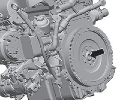
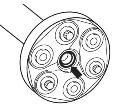
- Check the technical condition of the needle bearing in the crankshaft (arrow). Replace the needle bearing if necessary.
- Before final installation of the gearbox on the engine, check and ensure that the intermediate plate between the automatic transmission and the engine is installed properly.
- Apply a thin coat of high temperature grease to the needle bearing (arrow) and to the transmission input shaft (just not on the shaft splines).
- Apply a special lubricant to the shaft splines.
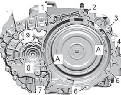
- Check and ensure that the guide bushings (A) for centering the gearbox on the engine are installed in the cylinder block.
1. Installation is carried out in the reverse order of removal, taking into account the conditions below.
2. Carefully lift the gearbox together with the engine and a special hydraulic jack. Adjust the position of the gearbox using the support plate. The gearbox is located approximately 30 mm away from the engine.
3. Do not pinch the cables and wiring harnesses between the gearbox and the cylinder block.
4. Connect the gearbox to the engine assembly. Install and tighten the gearbox-to-engine mounting bolts.
5. Connect the automatic transmission mode selection lever cable to its housing.
Note: Do not twist or bend the automatic transmission mode shift cable.
6. Connect the console to the transmission support assembly. To do this:
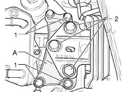
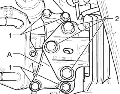
- Install the transmission console (A) between the transmission and the transmission support arm as shown in the figure below.
- Tighten the new transmission console (A) mounting bolts (1) as shown in the figure below.
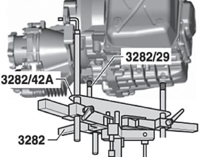
- Raise the gearbox evenly, hooking it onto a special device (MP9-200), and move it to the support lever of the automatic transmission support.
- Install and hand tighten the new mounting bolts (2) shown in the figure below.
Caution: Before screwing in the mounting bolts (2), the gearbox console and the gearbox support lever must be absolutely parallel to each other, otherwise the threads may be damaged.
7. Remove the special gearbox support (3282) from under the vehicle.
All-wheel drive models
Attention:
- Be extremely careful as there is a high risk of damage to the propeller shaft seal (arrow) shown in the figure below.
- When disconnecting, it is necessary to move the propeller shaft as far back as possible and towards the right side of the car.
8. Install and connect the cardan shaft assembly (for more details, see the relevant section in the chapter "Drive shafts").
9. Install the angular transmission mounting bracket, then install and tighten its mounting bolts to the required tightening torque.
Front-wheel drive models
10. Install the right flange of the drive shaft into the gearbox (for more details, see the relevant section in the chapter "Drive shafts").
Continued for all models
11. Connect the right and left drive shafts to the gearbox (for more details, see the corresponding section in the chapter "Drive shafts").
Front-wheel drive models
12. Install the inner constant velocity joint protective plate on the right side of the cylinder block. Install and tighten the plate mounting bolts to a torque of 35 Nm.
All-wheel drive models
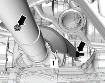
13. Install the drive shaft heat insulation cover as shown in the figure below. Tighten the mounting bolts (arrows).
Continued for all models
14. Install the subframe assembly (for more details, see the corresponding section in the chapter "Chassis").
15. Install (if provided) left front vehicle height sensor, automatic headlight aiming system.
Front-wheel drive models
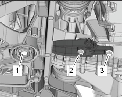
16. Install the rocker support and tighten the new mounting bolts (1, 2 and 3) to the required tightening torque, as shown in the figure below.
All-wheel drive models
17. Tighten the rocker support mounting bolts (2) and (3) as shown in the figure below to the required tightening torque.
Continued for all models
18. Install the starter and wiring harnesses (for more details, see the relevant section in the chapter "Engine electrical equipment").
19. Connect the wiring harness connector to the mechatronics module electronic control unit. To do this:
- The arrows on the mechatronics module and the wiring harness connector housing, as well as the protrusion, must be in line, as shown in the figure below.
- Connect the wiring harness connector by sliding it until it stops, then turn it in the direction of the arrow, thereby fixing its position, as shown in the figure below.
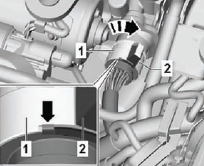
20. Assemble the exhaust pipe components of the vehicle's exhaust system. Eliminate stress in pipe joints (for more details, see the relevant section in the chapter "Intake and exhaust system").
21. Check the correct assembly of all power unit supports.
22. Tighten the new transmission console to transmission support arm mounting bolts to the specified torque.
23. Install the battery support plate, then install the battery (for more details, see the relevant section in the chapter "Engine electrical equipment").
24. Check that the automatic transmission mode selection cable is connected correctly and, if necessary, adjust it.
25. Install the air filter housing assembly (for more details, see the relevant section in the chapter Intake and Exhaust System).
26. Check the coolant level in the engine cooling system. If necessary, add coolant to the required level.
27. Check the transmission oil level in the gearbox. If necessary, add the required amount of transmission oil.
28. Install the front part of the left wheel arch liner.
29. Install the soundproofing engine compartment cover.
30. Install the front wheels. Install and tighten the front wheel mounting bolts.
- Adjust the position of the gearbox so that the engine and gearbox shafts are aligned and the engine and gearbox flanges match.
Note: When raising the gearbox, check the position of the selector cable. Insert the cable into the counter support as far as possible.
Do not lubricate the cable!
- The selector cable arrow lock washers must be replaced.
- Adjust the selector cable.
- Check and, if necessary, top up the coolant level.
- Check the oil level and top up the oil (for more details, see the relevant section in this chapter).
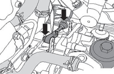
Tightening torques for threaded connections
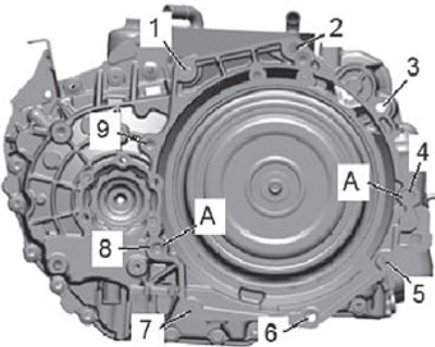
| Position | Screw | N m |
| 1 | M12x55 | 80 |
| 2 | M12x65 | 80 |
| 3 | M12x55 | 80 |
| 4 | M12x70 | 80 |
| 5, 6,7 | M10x50 | 40 |
| 8, 9 | M12x70 | 80 |
| A | centering bushings | |
Gearbox console assembly
Fastening bolt (1), tightening torque 40 Nm + tighten additionally by an angle of 90° (1/4 turn).
Fastening bolt (2), tightening torque 60 Nm + tighten additionally by an angle of 90° (1/4 turn).