Contents: Removal ⬇ Installation ⬇
Removal
1. Remove the engine trim panel assembly.
2. Remove the air filter housing assembly (for more details, see the corresponding section in the chapter "Intake and exhaust system").
3. Remove the battery and battery support shelf from the engine compartment (for more details, see the relevant section in the chapter "Engine electrical equipment").
Attention:
- Since electrolytic fluid is a corrosive acid and also toxic, please be careful when handling this fluid.
- Do not allow battery fluid to come into contact with skin, eyes or clothing.
- Especially in case of contact with eyes, rinse with water for 15 minutes and seek medical attention.
- Do not allow battery fluid to come into contact with painted surfaces of the vehicle.
- Because batteries produce explosive gases, use caution when working with batteries.
- Do not bring open flames close to the battery.
- When working near the battery, use eye protection, etc. to protect your eyes in case of explosion. Never tilt the battery.
- When using or charging the battery in an enclosed area, ensure adequate ventilation.
- Before starting work, remove rings, watches and other metal objects.
- When touching metal parts of a vehicle, never allow metal tools to come into contact with the positive battery terminal or allow any equipment to come into contact with the terminal.
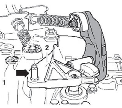
4. Remove the lock washer (1) shown in the figure below.
5. Move the gear shift cable retainer from the stud (arrow) of the gearbox lever (2), as shown in the figure below.
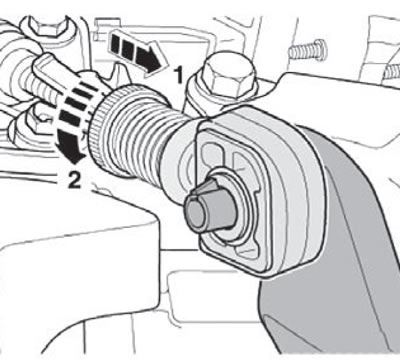
6. Move the cable locking mechanism forward until it stops in the direction of arrow 1, then turn it in the direction of arrow 2, as shown in the figure below.
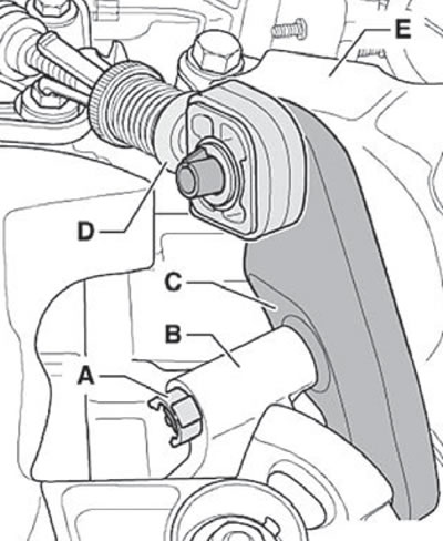
Note: The shift lever (C) can only be removed after removing the gearbox console (E).
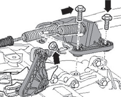
7. Unscrew the bolts and fastening nut (arrows) and remove the gear selection and engagement cable bracket, as shown in the figure below.
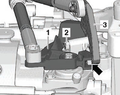
8. Remove the gear shift lever (1) shown in the figure below.
Note
- Transmission oil may leak.
- While performing work, make sure that there is no brake fluid on the surface of the subframe or side member. Clean surfaces if necessary.
9. Place a clean cloth under the parts to be removed.
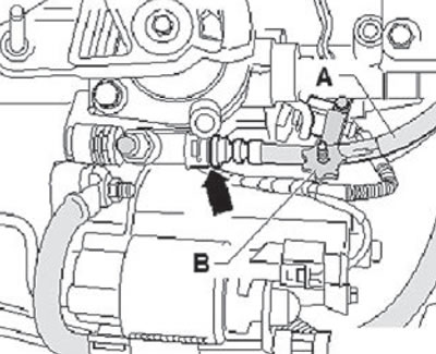
10. Using the special tool MP602 (B), pinch the master cylinder hose (A) as shown in the figure below.
11. Cover the bleed valve with a clean rag.
12. Remove the retainer (arrow) on the connection between the pipe and the hose until it stops upwards.
13. Disconnect the line from the bleed valve, plug it with a special plug and set it aside.
Note: After disconnecting the clutch release line, do not press the clutch pedal.
14. Disconnect the wiring harness connectors (1) and (2) shown in the figure.
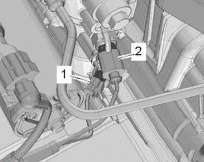
1. Transmission neutral position sensor; 2. Reverse lamp switch.
15. Unscrew the gearbox mounting bolts at the top (1) and (2).
16. Remove the soundproofing panels.
17. Remove the starter of the starting system (for more details, see the corresponding section in the chapter "Engine electrical equipment").
18. Remove the front wheel arch liners (for more details, see the corresponding section in the chapter "Body").
Note: To install the support device, the crossbar must be disconnected on the right side of the vehicle.
19. Unscrew the mounting bolts (arrows) and remove the cross member from the front body panel.
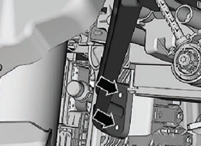
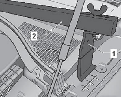
20. Install the adapter 10-222A/29 (1) on the body under the wing (on both sides of the car), as shown in the figure below.
Note:
- The adapter with the "L" symbol is installed on the right side of the vehicle.
- The adapter with the "P" symbol is installed on the left side of the vehicle.
- The arrow indicates the direction of the vehicle's movement.
21. Install a special device for hanging the 10-222A power unit together with other elements as shown in the figure below.
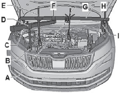
A. Adapter "MR9-200/3 (10-222A/3)" (models with diesel engines). B. Adapter "T40093 / 3-6" or "T40093/3-6A". C. Support part "T40091/1". D. Spindle "T40093/3". E. Hook for fitting MR9-200 and T30099 "MR9-200/10 (10-222A/10)". F. Coupling "T40091/3". G. Hook for MP9-200 and T30099 "MP9-200/10(10-222A/10)". N. Crossbar for hanging the MP9-200 power unit. I. Adapter "10-222A/29"
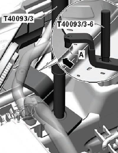
22. Install the adapter -T40093/3-6- or -T40093/3-6A- on the body panel, as shown in the figure below.
- The adapter "T40093/3-6" or "T40093/3-6A" must be secured with the mounting bolt (A) on the body panel flange (arrow).
- Connect the adapter "T40093/3-6" or "T40093/3-6A" to the spindle "T40093/3" of the crossbar and pre-tension the crossbar.
23. Slowly lift the power unit assembly, together with the hooks MP9/200 and T30099 "MP9 200/100 (10-222A/10)".
24. Disconnect the wiring harness connector (1) from the engine oil level and temperature sensor as shown in the figure below.
25. Remove the front suspension subframe assembly with the steering gear (for more details, see the corresponding section in the chapter "Chassis").
Attention:
- To prevent injury and/or component damage, do not allow the weight of the vehicle to be loaded onto the front wheels or operate the vehicle with the drive shaft nut loose. This could cause the inner bearing race to separate, causing damage to brake or suspension components and causing loss of vehicle control.
- Drive shaft boots, seals and clamps must be protected from sharp objects when servicing the drive shaft or components located near it. Damage to the anthers, seals or clamps can cause the joint to become depressurized, which will lead to extraneous noise and possible drive shaft failure.
- Unscrew the bolts securing the longitudinal support of the power unit assembly.
- Loosen the hexagonal nut securing the stabilizer bar pin (perform this operation on both sides).
- Disconnect the strut from the anti-roll bar on the left and right sides.
- Loosen the nuts securing the lower arm of the front suspension to the ball joint of the steering knuckle.
Cars with a height sensor
- Disconnect the wiring harness connector from the left front height sensor or the right front height sensor.
For all models
- Pull towards you and disconnect the wiring harness clamps from the subframe and from the steering rack.
- Unscrew the steering rack mounting bolts.
- Remove the steering rack from the guide pins and disconnect it from the front suspension subframe.
- Place a special hydraulic jack with a support platform under the subframe and the front suspension.
- Fix the position of the subframe on the platform of the hydraulic jack and lower it together with the jack by approximately 10 mm.
- Remove the retainer shown in the figure below (arrow).
- Lower the subframe assembly using a hydraulic jack.
- Secure the front suspension subframe to the support platform of a hydraulic jack.
- Fix the position of the steering rack on the car body.
- Lower the jack together with the subframe assembly.
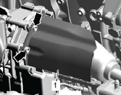
26. Unscrew the mounting bolts and remove the protective cover of the right drive shaft, as shown in the figure below.
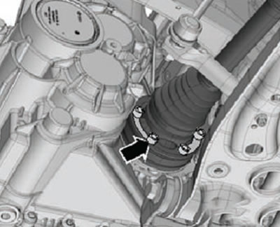
27. Unscrew the mounting bolts (arrows) and remove the right and left drive shafts from the gearbox, as shown in the figure below.
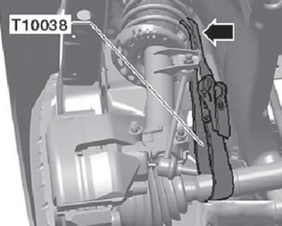
28. Hang both drive shafts using special mounting straps from the front suspension shock absorber struts, as shown in the figure below.
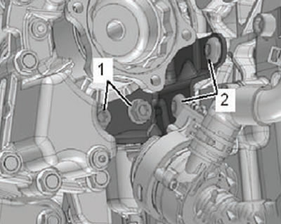
29. Unscrew the mounting bolts (1), (2) and remove the angular transmission mounting bracket, as shown in the figure below.
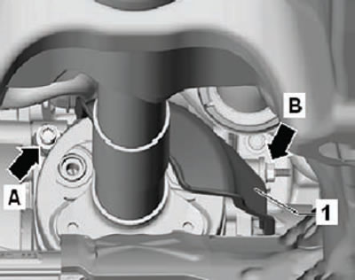
30. Unscrew the mounting bolts (A) and (B), then remove the propeller shaft protective plate (1), as shown in the figure below.
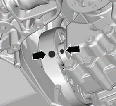
31. Mark the relative position (arrows) of the elastic disc and flange on the angular gearbox as shown in the figure below.
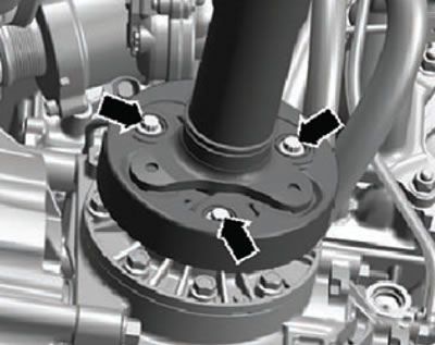
32. Unscrew the mounting bolts and disconnect the propeller shaft (arrows) from the angular gearbox.
33. Move the power unit assembly forward slightly (towards the front of the car), to disconnect the cardan shaft from the angular transmission flange.
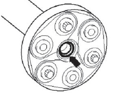
Note: Make sure that the sealing ring (arrow) in the propeller shaft flange is not damaged during removal and installation.
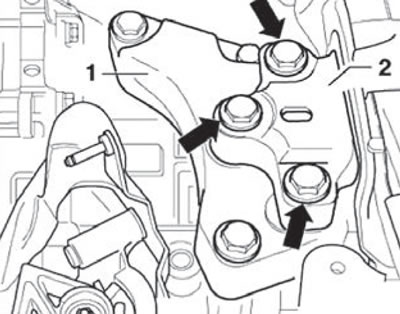
34. Unscrew and remove the mounting bolts (arrows) of the left engine support (2), as shown in the figure below.
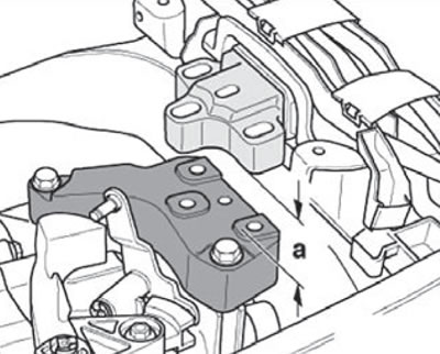
35. Lower the power unit assembly using the crosshead spindles. Lower by approximately 60 mm (a).
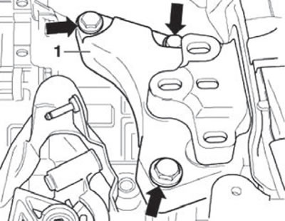
36. Unscrew the mounting bolts (arrows) of the gearbox console (1).
37. Remove the gearbox console assembly (1).
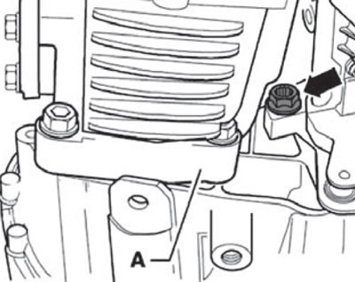
38. Unscrew the connecting bolt of the power unit and angular transmission (arrow).
Information copied from the resource: SkodaBook.ru
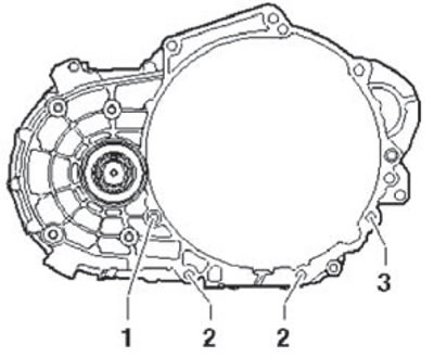
39. Loosen the connecting mounting bolts (2) and (3). Leave them screwed in by hand.
- The connecting bolt (1) was unscrewed earlier.
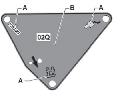
40. Install the special support "3282" on a special jack.
41. Install the adjusting plate "3282/62" onto the support "3282".
Note:
- The adjustment plate can only be set to one position.
- The arrow on the adjustment plate must point in the direction of the vehicle.
42. Align the gearbox support levers with the holes in the adjusting plate.
43. Screw in the support elements (A) as shown in the figure below.
44. Place the power unit jack under the vehicle.
45. Install the adjusting plate parallel to the gearbox.
46. Fix the adapter -MRZ-419/40- (C) in the threaded hole of the gearbox housing, as shown in the figure below.
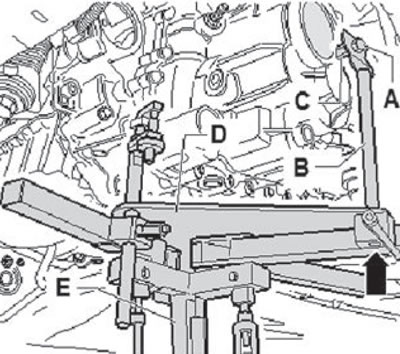
A. Bolt M10 x 20. B. Adapter for gearbox support "3282". C. Adapter "MRZ-419/40". D. Adjusting plate "3282/62". E. Gearbox support "3282"
47. Secure the gearbox support adapter 3282 (B) using the bolt (A).
48. Guide the adapter mandrel (B) into the guide of the gearbox support 3282 (arrow) and fix it in this position.
49. Screw bolt 3282/29 into the hole to secure the gearbox support.
50. Unscrew the remaining gearbox mounting bolts.
51. Press to separate the gearbox from the engine block.
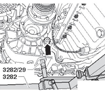
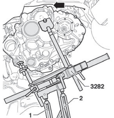
52. Lower the gearbox very carefully, if necessary, tilt it using spindles (1) and (2) of support 3282.
Installation
Installation is carried out in the reverse order of removal.
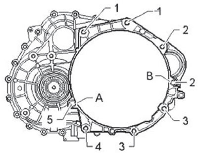
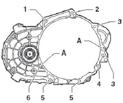
Tightening torques for fastening elements to the cylinder block:
| Number | Bolt | Quantity | Tightening torque Nm |
| 1 | M12x50 | 2 | 80 |
| 2 | M12x170 | 2 | 80 |
| 3 | M10x50 | 2 | 40 |
| 4 | M10x65 | 1 | 40 |
| 5 | M12x65 | 1 | 80 |