
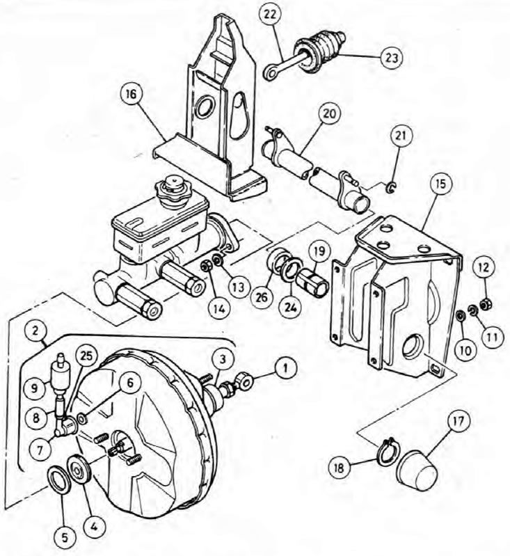
Pic. 9.4. Brake Pedal and Vacuum Booster/Master Cylinder Link Assembly
1. Amplifier push rod and threaded regulator; 2. Assembling the vacuum booster unit; 3. Rubber boot; 4. Seal; 5. Washer; 6. O-ring; 7. Hose coupling; 8. Hose; 9. Non-return control valve; 10. Washer; 11. Spring washer; 12. Nut; 13. Spring washer; 14. Nut; 15. Left arm of the thrust; 16. Right arm of thrust; 17. Dust cover; 18. Retaining ring; 19. Articulated bushing; 20. Traverse rod; 21. Blocking bracket; 22. Pedal drive rod; 23. Rubber boot; 24. Washer; 25. Staple; 26. Seal (models released since 1992).
Removing
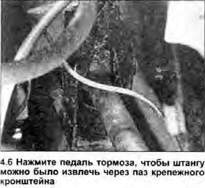
1. Remove the vacuum booster block. if you want to make the process easier (see chapter 5). If the booster remains in the link mounting bracket, remove the locking bracket that secures the booster push rod lug to the link rod. Have an assistant depress the brake pedal to gain access through the slot in the side of the mounting bracket.
2. Remove the dust cover and remove the circlip from the left end of the pedal link cross bar.
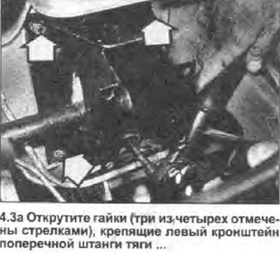
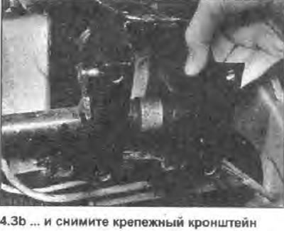
3. Loosen the nuts securing the left cross-rod bracket to the bulkhead, then remove the bracket from the end of the rod; pay attention to the pivot sleeve, washer and (on models manufactured since 1992.) seal (see photo). If the vacuum booster unit is still attached to the bracket, very carefully (see chapter 5) Unhook the booster push rod from the pedal cross rod, being careful not to bend or damage the metal brake pipes.
 |  |
4. Have an assistant depress the brake pedal to gain access through the slot in the right bracket sidewall and remove the locking bracket that secures the drive link eye to the pedal link cross bar pin.
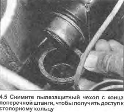
5. Remove the dust cover and remove the retaining ring from the right end of the pedal cross bar (see photo).
6. Remove the transverse link rod from the right bracket; also take the swivel sleeve and washer (see photo).
7. If the right tie rod bracket needs to be removed, note that the nuts securing it to the bulkhead also secure the pedal bracket to the interior of the vehicle. Either lock the pedal bracket in position so as not to disturb the pedals, or disconnect the throttle and clutch cables (see Sections 4 and 6 respectively) and brake light switch wires (see Chapter 27), so that the assembly can be removed.
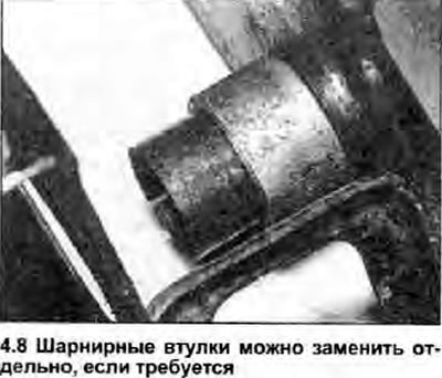
8. Clean all components and check running surfaces and hinges for damage and signs of wear. Replace any worn or damaged components - pivot bushings sold separately (see photo).
Installation
9. Install in the reverse order of removal paying attention to the following:
- a) Apply a light coat of multipurpose grease to all hinges and work surfaces.
- b) Tighten all nuts and bolts with a tightening torque specified specifications (where given).
- c) Check and adjust, if necessary, the height of the brake pedal (see chapter 3).