
Removing
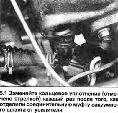
1. Open the hood and disconnect the hose from the vacuum booster unit (see photo).
2. Turn off two nuts fixing the main cylinder to the block of the vacuum amplifier.
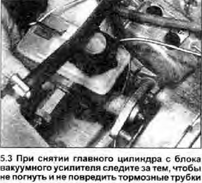
3. Very carefully move the master cylinder forward to release the booster pins and master cylinder primary piston rod. Be careful not to bend or damage the metal brake pipes. If there is even the slightest risk of such damage, release the tubes from the mounts on the baffle or disconnect them (see chapter 11), until you remove the master cylinder (see photo).
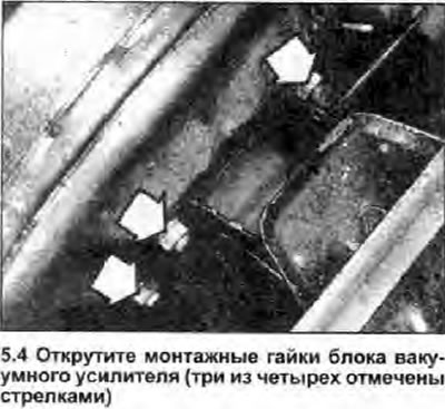
4. Unscrew the four nuts securing the vacuum booster unit to its bracket (see photo).
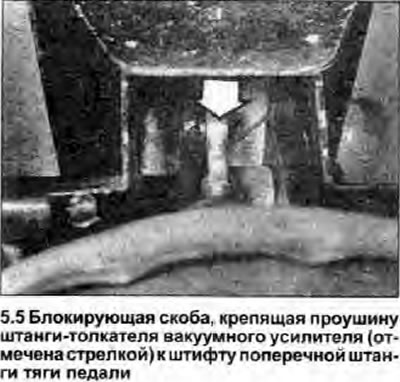
5. After asking an assistant to depress the brake pedal, move the vacuum booster block away from the mounting bracket so that the locking bracket that secures the booster pushrod lug to the pedal cross bar pin can be removed. Do not bend the push rod, otherwise the piston associated with it may be damaged; carefully move the entire vacuum booster assembly to disengage the push rod from the pin (see photo).
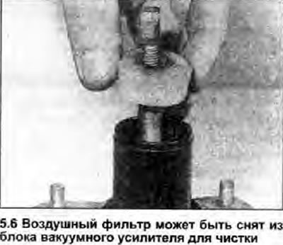
6. If the block is defective, replace it (see note given in Chapter 1). The booster push rod rubber boot can be replaced separately, as can the washer and seal of the master cylinder primary piston rod. The amplifier air filter can be cleaned. if it is contaminated. If any other component is damaged (including air filter), it can only be replaced as part of a complete amplifier assembly (see photo).
Installation
7. Install in the reverse order of removal, paying attention to the following (see photo):
 |  |
 |
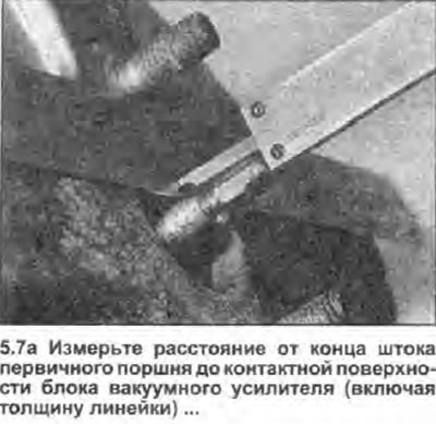
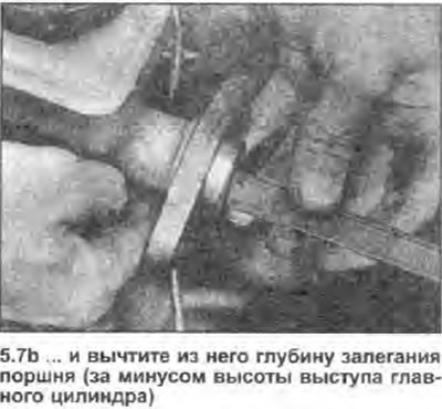
- a) On early models (identification number of the vacuum booster unit 443.613.000.003), make sure that there is a gap of 0.3-0.6 mm between the end of the primary piston rod coming from the booster and the master cylinder primary piston itself. To do this, measure the distance from the end of the piston rod to the contact surface of the booster and subtract from the obtained value the depth of the piston from the contact surface of the master cylinder. To get this depth, measure the distance from the end face of the master cylinder boss to the piston, then subtract the height of the boss above the cylinder contact surface. If the clearance requires adjustment, install a double-sided wrench on the chamfers of the primary piston rod and. while holding the stem in this way, screw in or unscrew its tip until you reach the desired length of the protruding part of the stem.
- b) On late models (identification number of the vacuum booster unit 443.613.000.011) an unadjustable master cylinder primary piston rod is used. Gap between piston rod and primary piston (0.3mm) installed during the assembly process of the car and supported by the arrangement of components (see note. given in Chapter 1).
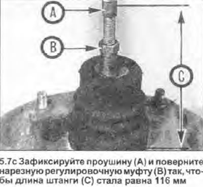
- c) On all models, if a new amplifier is installed (or if this adjustment was violated for some reason), make sure that the center of the lug of the booster push rod is 116 mm from the contact surface of the block (distance «WITH» in photo 5.7s). If adjustment is necessary, turn the threaded boom adjusting collar to the desired direction. This will provide a basic brake pedal height accurate enough to serve as a starting point for final pedal adjustment after the unit is installed.
- d) Apply a light coat of multipurpose grease to all hinges and work surfaces.
- e) Install the booster with the vacuum hose coupler to the center tube of the car, being careful not to bend the booster rod. Be sure to change the O-ring of the vacuum hose connector after each removal.
- f) Tighten nuts and bolts with a tightening torque specified specifications (where given).
- g) If the brake pipes have been disconnected, bleed the brake hydraulic system (see chapter 9) and clean up any spilled brake fluid. Check the restored joints of the system for tightness.
- h) Check and adjust, if necessary, the height of the brake pedal (see chapter 3).
- i) Check the operation of the brakes in general and the vacuum booster unit in particular.