



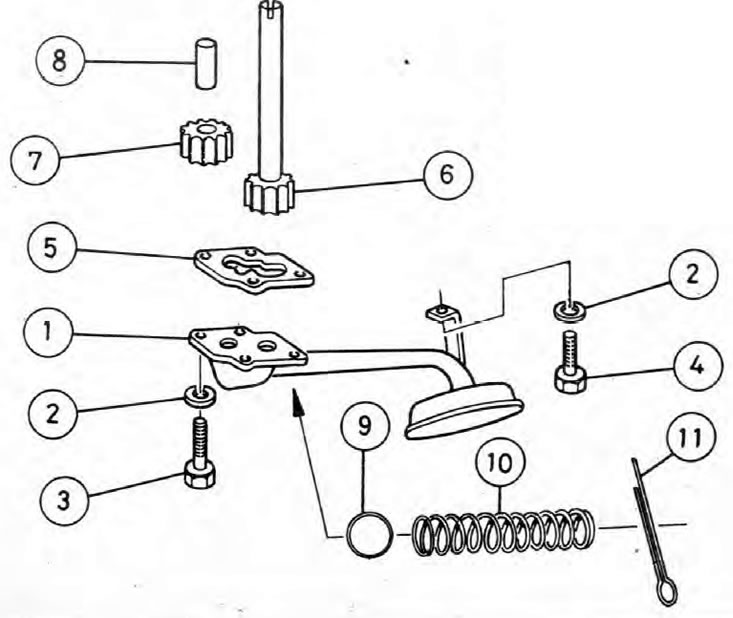
Fig. 2A.6. Oil pump components
1. Oil pump suction pipe/strainer; 2. Spring washer; 3. Bolt - receiving tube to the drive cover; 4. Bolt - intake pipe/mesh filter to bearing cap; 5. Gasket (where is available); 6. Oil pump drive gear; 7. Oil pump driven gear; 8. Oil pump driven gear shaft; 9. Ball of the pressure reducing oil valve; 10. Spring of the pressure reducing oil valve; 11. Hairpin.
Removal
1. Remove the tray as described in Chapter 10.
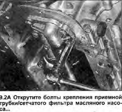
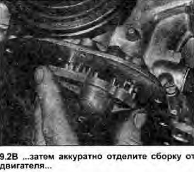
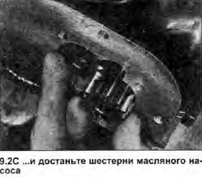
2. Remove the four bolts securing the oil pump pickup tube to the back of the drive cover and the one bolt securing it to the center main bearing cap. Carefully separate the pickup tube/strainer from the drive cover. Be careful, the oil pump gears will fall out once the cover is removed (see illustrations). Remove the gasket (where is available) - it is subject to replacement.
 |
 |
 |
Inspection
3. Inspect the gears and oil pump housing for worn spots or damage. If you have the necessary measuring instruments, you can determine the degree of wear on the shafts and pump housing. If the amount of wear exceeds the permissible limits, Specifications values, pump gears and main drive chain cover (which includes the oil pump housing) must be replaced as a set. For information on removing and installing the timing chain cover, see Chapter 7.
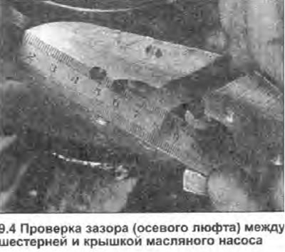
4. Temporarily insert the gears into the pump housing and using an edge-mounted ruler and feeler gauges measure the clearance (axial play) between the gear and the cover (see illustration). Skoda states that the gap between the gears and the cover should be no more than 0.1 mm. If the gap is approximately 0.1 mm, the intake pipe/strainer must be installed without a gasket. If the gap is very small or does not exist at all, then a gasket of suitable thickness must be installed behind the cover. If the gap exceeds 0.1 mm, the pump housing and/or gears are worn and the oil pump assembly must be replaced.
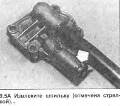
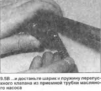
5. Remove the pin from the oil pump intake tube/strainer, and take out the pressure relief valve spring and ball (see illustrations). Inspect them for damage or signs of wear, and replace as necessary. If a new ball is installed, insert it into the intake tube, then use a hammer and a suitable soft metal drift to tap it into place; this will ensure that the valve functions correctly. Finally, secure the ball and spring with a new pin.
 |
 |
Installation
6. Where necessary, place a new gasket on the mating surface of the oil pickup tube assembly.
7. Generously lubricate the gears and shafts of the oil pump, then insert the gears into the housing. Install the oil pump suction tube/strainer, and insert the five mounting bolts. Tighten the mounting bolts to the specified torque Specifications.
8. Install the tray as described in Chapter 10.