



Removal
1. Remove the rocker arm shaft assembly.
2. Remove the pushrods one by one and store them in the order they were installed on the engine in a specially prepared box divided into sections. Note that the pushrods for the intake valves are made of aluminum, while the exhaust valves are cast iron.
3. Loosen the four nuts securing the tappet cover to the front side of the cylinder block. Remove the washers and sealing bushings from the studs. Carefully pry the cover off the block and remove it along with the rubber sealing gasket.
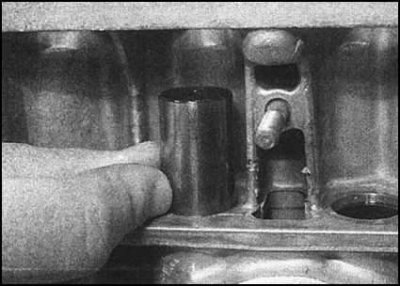
4. Remove the pushers...
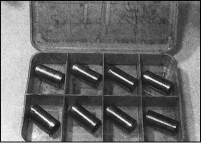
...and place them each on its own rod. Remove the tappets and store them in the order of their original installation. Installation of usable components on the engine should be carried out strictly in the original order in order to minimize the rate of wear of the working projections of the camshaft cams.
5. Remove the timing chain and sprockets.
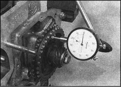
6. Before removing the camshaft, estimate its axial play by temporarily installing the distributor/oil pump drive gear, disc and lock washers and screwing the bolt into the end of the shaft journal, tightening it to the required force. Now, using a plunger-type dial gauge, estimate the axial play of the shaft by measuring its free play in the longitudinal direction.
7. If the measurement result exceeds the specified Specifications acceptable value, during assembly the shaft thrust plate should be replaced.
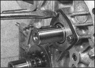
8. Remove the components temporarily installed for checking the axial play, then unscrew the three screws securing the camshaft thrust plate to the cylinder block...
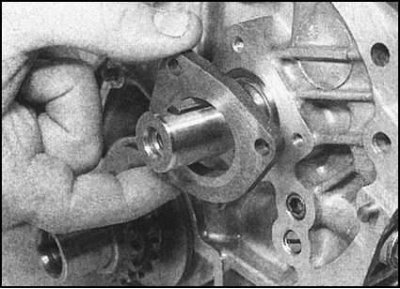
... Remove the plate...
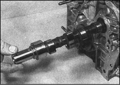
...and remove the shaft from the block.
Examination
1. Assess the degree of wear of the working surfaces of the tappets in contact with the camshaft cams.
2. When inserting each of the tappets into its seat in the block, check the freedom of their seating. The tappets should move smoothly along their axis, but should not have excessive lateral play.
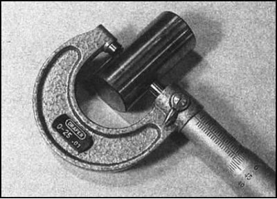
3. If the necessary equipment is available, the clearance of the tappets in the sockets can be determined by direct measurements.
4. Excessively worn (compare measurement results with requirements Specifications), or damaged tappets must be replaced.
5. If the tappets fit excessively loosely in the sockets, or if signs of wear of the latter exceed the permissible limit are detected, the block should be re-machined and the tappets should be replaced with new ones of repair size (in excess).
6. Check the condition of the cams and journals of the camshaft. If defects are found on the surface of the journals, also evaluate the condition of the corresponding bearings in the block body.
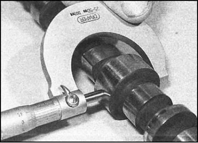
7. If you have the necessary equipment, measure the diameters of the shaft journals, as well as the diameters of the bearings in the block. By subtracting the results of the first measurement from the last, determine the size of the working clearances in the bearings and compare the results with the requirements Specifications.
8. If signs of serious wear of the journals or cams are detected, the shaft must be replaced. If the bearings are worn (compare the results of measuring their diameters with those specified in Specifications), it is necessary to consider the possibility of turning the block and then replacing the liners with repair ones. If turning is not possible, the block will have to be replaced.
9. Check the condition of the camshaft thrust plate. If signs of wear are detected, replace the plate.
Installation
1. After generously lubricating the journals and cams of the valve drive with engine oil, insert the camshaft into the cylinder block.
2. Place the thrust plate on the shaft journal and secure it to the cylinder block with three screws. Repeat the shaft axial play check. Install the thrust washer and check the axial play.
3. Install the timing chain and sprockets in place.
4. Lubricate the outer surfaces of the tappets with oil and insert each one into its own seat in the block.
5. Check the condition of the rubber sealing gasket of the tappet cover. If there are no defects, the old gasket can be used further.
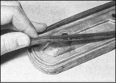
6. Thoroughly wipe the mating surfaces of the block and cover, then carefully insert the gasket into the groove on the inside of the cover.
7. Install the cover on the block - try not to move or twist the gasket.
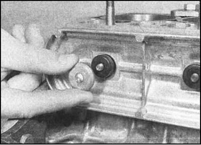
8. Place sealing bushings and washers on the studs,...
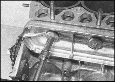
... then screw on the nuts and tighten them to the required torque.
9. Install the push rods in their original places. Make sure they are positioned correctly in their push rods.
10. Install the rocker arm shaft assembly, adjust the valve clearances (see Chapter Routine maintenance), then install the cylinder head cover back into place.