



Contents: Disassembly ⬇ Cleaning ⬇ Checking the status ⬇ Lapping valves ⬇ Assembly - 1.3L engine ⬇ Assembly - 1.6 l and diesel engines ⬇ Petrol engines 1.6 l ⬇ Diesel engines ⬇ All engines ⬇
Note: In Skoda branded service centers, you can always order a restored head, which is often much more practical than spending time and effort on performing fairly complex procedures for checking and restoring the old one.
Disassembly
Engines 1.3 l
1. Using a special tool, alternately compress the springs of each valve, removing the split lock crackers from their rods. Releasing the tool, remove the spring plates and the springs themselves from the valves (internal and external).
2. If the plate does not give way when the spring is compressed and does not provide access to the crackers, lightly tap the tool holder with a light hammer.
3. Remove the outer and inner spring seats from the guide bushing, then use pliers to carefully remove the oil deflector cap from the bushing.
4. Remove the valve through the combustion chamber.
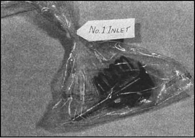
5. If the valves and related components are in satisfactory condition, the parts should be folded in the order they were installed on the engine, placing them in separate, specially marked bags.
1.6L and diesel engines
1. On a diesel engine, remove the fuel injection nozzles and glow plugs (see Chapters Power supply system and Engine electrical equipment). Remove the outlet elbow of the cooling system pipe with the gasket/sealing ring.
2. On a 1.6 l engine, unscrew the thermostat housing and oil pressure switch from the cylinder head.
3. Remove the timing belt toothed wheel from the camshaft journal.
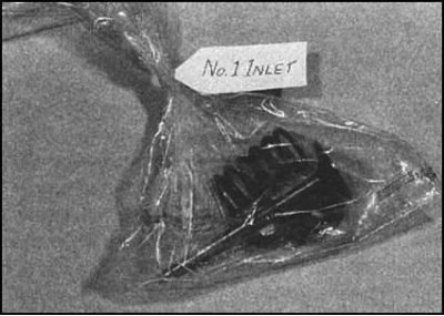
4. Prepare specially marked bags for storing the valve mechanism components to be removed. Installing the components in a random order will result in accelerated wear of the parts and premature failure of the entire mechanism.
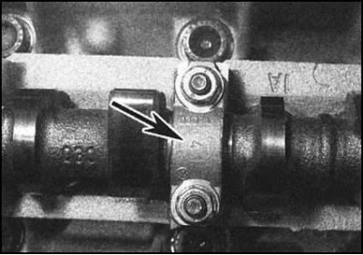
5. Check the camshaft bearing caps for factory markings. If necessary, apply marks yourself with a scriber or center punch. Loosen the bearing cap fastening nuts gradually and evenly to avoid creating internal stress in the shaft body. The procedure for loosening the fasteners is described below.
6. First loosen the nuts of bearing caps No.5, 1 and 3. Then move on to the caps of bearings No.2 and 4. Loosen diagonally in several steps (half a turn per approach) until it becomes possible to release the nuts manually.
Note: The covers are numbered sequentially (1 through 5) from the timing belt side.
7. Remove the old oil seal from the camshaft journal facing the timing drive. The oil seal must be replaced during assembly.
8. Carefully, trying not to tilt it, remove the camshaft from the head. Support the shaft at both ends and make sure that its cams and bearing journals do not catch on the protrusions in the head body.
9. Remove the hydraulic lifters from their seats and stack them in the order they were installed on the engine, with the valve contact surface facing down to prevent oil leakage. Alternatively, the lifters can be placed in oil-filled containers. Remember that installing the lifters in a random order during assembly will result in accelerated component wear and premature valve train failure.
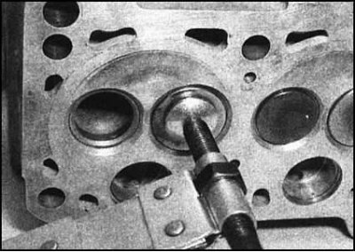
10. Turn the head over and place it sideways on the workbench. Using a special tool, alternately compress the spring of each of the valves and remove the crackers of the split locks. If the spring seat "sticks", tap the upper jaws of the tool with a light hammer.
 |
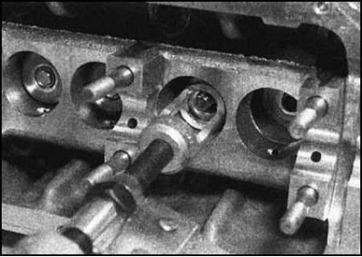 |
11. Release the tool and remove the upper seat and the spring itself.
12. Use pliers to remove the seal from the valve stem. Remove the valve from the head (from the side of the surface mating with the block). If the valve is jammed in the guide bushing, carefully sand its end surface with sandpaper. Proceeding in the same order, remove all remaining valves.
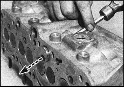
13. On a diesel engine, the swirl chambers should be checked for burnouts and traces of coking. If necessary, carefully knock out the defective chamber by inserting a punch into the hole of the corresponding injector.
Cleaning
1. Thoroughly clean the head with solvent, removing all traces of oil deposits. Pay particular attention to the condition of the camshaft journals, tappet seats and valve guides. Carefully scrape off all traces of old gasket material from the mating surface of the head. Turn the head over and use a blunt knife to remove carbon deposits from the surfaces of the combustion chambers and intake ports.
Caution! Try to avoid erosion of the valve seat surfaces. Finally, wash the entire head with a suitable solvent, completely removing all traces of abrasive.
2. Use a fine wire brush to clean the valve plates and stems, after scraping off most of the carbon deposits with a blunt knife.
Caution! Try to avoid erosion of the working surfaces of the valve plates.
3. Using solvent, thoroughly wipe all other removed components. Then dry them thoroughly. Prepare replacement seals/valve caps.
Checking the status
Head casting
Note: Repair of valves and diesel head is not possible (except for grinding). In case of damage or wear, components must be replaced.
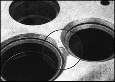
1. Carefully inspect the head casting, checking for cracks in the area of the mounting holes, valve seats and spark plug niches. If defects in the bridges between the seats of adjacent valves are detected, consult with car service specialists.
2. Check the condition of the working chamfers of the valve seats. Minor defects can be eliminated by grinding the valves. In case of detection of deep cavities, cracks, traces of burnout and other serious defects, restoration of the head becomes possible only in the conditions of a car service workshop.
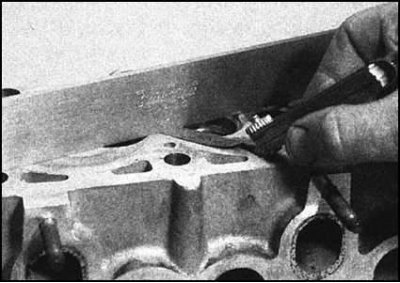
3. Check the flatness of the mating surfaces of the head with the block, intake manifold and exhaust manifold. Take measurements along the diagonals of the surfaces. Compare the results with the requirements Specifications. On gasoline engines, minor unevenness can be corrected using sandpaper.
4. Requirements for the minimum permissible height of the cylinder head are also given in Specifications. When performing head turning, do not forget about the following points:
- a) Head turning is permitted only while maintaining the minimum installation height (if specified - see. Specifications);
- b) After completing the machining, the mating surfaces must also be chamfered on the valve seats to match the new head height. Failure to do so may result in damage to components due to the valves colliding with the piston crowns;
- c) Before proceeding with turning the valve seats, make sure that there is a sufficient reserve of material to perform the repair. Removing an excessively thick layer may result in the valve stems protruding too much above the ends of the guide bushings and, as a consequence, in the malfunction of the hydraulic tappets. Consult with specialists.
Note! For some engine modifications, replacement valves of shortened length can be purchased - contact Skoda branded service centers.
Camshaft - 1.6L and Diesel Engines
Note: For 1.3L models, refer to Section 1 for camshaft removal and installation procedures Removal and installation the timing belt and its covers.
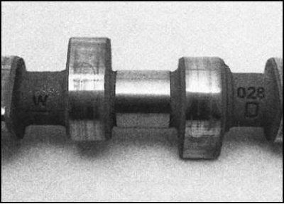
1. The camshaft is provided with identification markings in the form of marks stamped on its sides between the cams of the intake and exhaust valves. The markings can be decoded by specialists of the Skoda branded service center.
2. Visually inspect the camshaft for signs of wear and other defects on the working surfaces of the cams and journals. The surfaces should be absolutely smooth and have a slightly dull polish. The presence of scratches, burrs, cavities or areas polished to a shine indicates that the shaft is approaching the end of its service life. As soon as the surface hardening layer is damaged, the shaft wears out quickly and should such signs be detected, it should be replaced.
Note: If defects are found on the cams, also check the condition of the contact surfaces of the corresponding hydraulic tappets.
3. On diesel engines, assess the degree of wear of the vacuum pump drive gear.
4. If signs of overheating of the machined surfaces of the shaft are detected (discoloration or bluish coloration), it is necessary to assume a possible malfunction of the lubrication system. Overheating often leads to deformation of the shaft, so it is necessary to determine the value of its runout. Place the shaft with its journals in the recesses of two V-shaped blocks and measure the runout value on the central neck using a plunger-type dial gauge. If the measurement result exceeds the specified value, Specifications acceptable value, the shaft must be replaced.
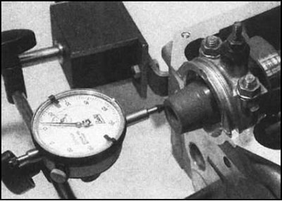
5. To assess the axial play of the camshaft, temporarily place it back in the cylinder head and install the first and last bearing caps, tightening their mounting nuts to the required torque. Attach a dial gauge to the front journal side of the shaft (facing the timing belt location), parallel to the shaft axis. Push the shaft back as far as it will go (towards the flywheel location), press the plunger of the gauge against the end of the front journal and zero the gauge. Now move the shaft forward over its full stroke and read the gauge. Verify that the check is correct by moving the shaft back again and making sure that the gauge pointer returns to zero.
Note: Checking the axial clearance of the camshaft must be carried out with the hydraulic valve lifters removed from the head.
6. Compare the result of the check is beyond the limits specified in Specifications acceptable range, you should consider options for upcoming replacements of the head, shaft and its bearing caps - consult with car service specialists.
7. The difference between the diameters of the bearings and the shaft journals determines the size of the working clearances in the bearings and should also not go beyond the permissible range.
8. The diameter of the shaft journals is not specified by the manufacturers, therefore the authors of this Manual do not recommend performing this check by direct measurements using a micrometer and bore gauge.
9. A more suitable method for assessing bearing clearances in this case is to check using a special Plastigauge kit. The clearance size is determined by the degree of flattening of the soft calibrated wire sections from the kit when compressed between the working surfaces of the bearings and the shaft journals. The width of the flattened wire sections is measured using the scale printed on the kit packaging.
10. Below is a detailed step-by-step description of how to perform this check. It should be noted that the same method is used to determine the working clearances in the main and connecting rod bearings of the crankshaft (see section Removal and installation the cylinder head assembly with the intake manifold and exhaust manifold).
11. Make sure that the working surfaces of the camshaft, cylinder head and bearing caps are absolutely clean and dry. Install the shaft in its regular place in the head.
12. Place pieces of calibrated wire from the kit along the shaft journals.
13. Lightly lubricate the bearing surfaces of each cover with a special silicone compound to prevent wire sticking. Install the covers in their places and tighten the nuts to the required torque (see the instructions in the "Assembly" subsection).
Note: If step tightening of fasteners is provided, tighten nuts to the first stage force only. Do not allow the shaft to turn after installing the covers.
14. Carefully remove the lids, lifting them strictly vertically so as not to disturb the shape of the flattened sections of wire. If the wire, despite the measures taken, has stuck to the working surfaces of the lids, the procedure will have to be repeated.
15. Measure the width of the flattened wire sections using the scale on the kit packaging. The scale is graduated in such a way that the reading taken is directly equal to the size of the gap being determined.
16. Compare the results obtained with the requirements Specifications. If the clearances exceed the permissible limits, the camshaft and cylinder head must be replaced. Note that in Skoda branded service centers you can order a repair-size camshaft with a set of corresponding liners, but only in a set with a replacement head.
17. Finally, remove the shaft and remove all traces of flattened calibrated wire from its journals and the working surfaces of the covers by carefully scraping them off with the edge of a credit or payphone card. Then wipe the surfaces, finally cleaning them from silicone residues.
Valves and related components
Note: None of the engines are designed for valve head turning. The only acceptable way to restore seal quality is to grind the valves to their seats. If this grinding fails to achieve a satisfactory result, the valves should be replaced.

1. Carefully inspect each valve, assessing the degree of wear. Check the valve stems for signs of step wear, scratches, scoring, and other mechanical damage. Using a micrometer, measure the diameter of each stem in several places.
2. Check the valve plates for cracks, cavities and burn marks. Minor defects can be eliminated during the grinding process (see below), in case of more serious wear the valves must be replaced.
3. Check the condition of the end surfaces of the valve stems. The presence of deep cavities and other similar defects on them may be due to a malfunction of the hydraulic tappets (1.6L and diesel engines).
4. By placing the valves one by one in a V-shaped block, use a dial gauge to assess the amount of runout of their plates. The manufacturers do not specify acceptable values, but if the runout is noticeable, the defective valve should be replaced.
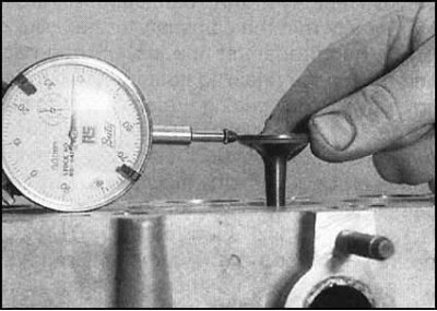
5. After inserting the valve into the appropriate guide bushing, again using a dial gauge, estimate the size of its seating clearance. The end of the valve stem during measurement should be flush with the upper edge of the bushing.
6. If there is excessive play in the valve sleeve, both components (and the valve and the bushing) are subject to replacement.
Note: The guide bushings are press-fitted into their seats in the cylinder head and a hydraulic press will be required to remove them, so it is best to leave this work to a service station.
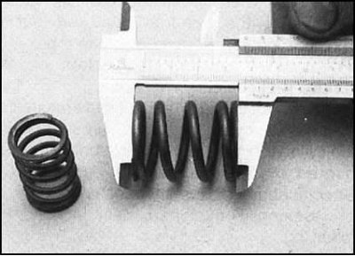
7. Using a vernier caliper, measure the free length of each valve spring. Since manufacturers do not specify acceptable spring lengths, the only way to check their condition is to compare the measurement results with the length of a new spring. The authors of this Manual recommend replacing valve springs during an engine overhaul, regardless of their condition.
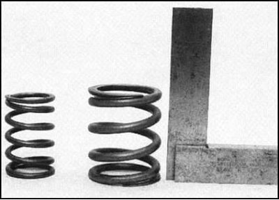
8. After installing the spring vertically, evaluate the quality of its trimming. Replace it if necessary.
9. By loading the valves with special weights, evaluate the magnitude of the force developed by the springs. It is better to entrust this check to specialists at the service station. Installing sagging springs leads to an increase in the overall noise level of the engine and a decrease in the compression pressure in the cylinders.
Lapping valves
1. Restoration of the lost valve closing density is performed by grinding them to their seats. Grinding is performed using several gradations of grinding paste and a device for gripping the valve with a suction cup.
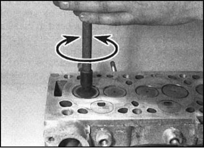
2. Apply a small amount of fine lapping paste to the sealing surfaces of the cylinder head. Turn the head upside down with the combustion chambers facing upwards and insert the valve into the corresponding guide bushing. Attach the suction cup to the valve plate plane and begin to lap it with the working chamfer to the seat using reciprocating rotational movements. Raise the valve from time to time to redistribute the paste.
3. Continue lapping until a continuous ring of matte polish of uniform thickness appears on the seat chamfer surface. Repeat the procedure for each of the remaining valves.
4. In case of severe damage to the working chamfers, lapping should be started with a coarse-grained paste at the first stage, gradually moving on to finer gradations. It is necessary to make sure in advance that the residual thickness of the plate and seat allows for sufficiently deep lapping. On 1.6 l models and diesel engines, when removing an excessively thick layer of material, there is a risk of the valve stems protruding too much above the cuts of the guide bushings, which is fraught with malfunction of the hydraulic tappets. Before starting lapping, consult with car service specialists.
5. After completing the first stage of grinding (with coarse paste) thoroughly wash off traces of abrasive with solvent, then move on to a finer paste.
6. After finishing lapping, wash the head and valves with solvent and dry the components thoroughly.
(Information copied from the resource: skodabook)
Assembly - 1.3L engine
Attention! When using old components, they must be installed on the engine strictly in the same order. This condition also comes into force after finishing the grinding of new valves - they must be installed in the head strictly in the same seats to which they were ground.
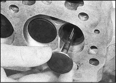
1. Lubricate the valve stems and insert them into the appropriate guide bushings.
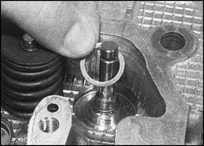
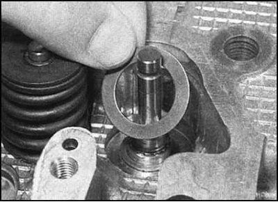
2. Starting with the first valve, place the seats of the inner spring, then the outer spring.
 |
 |
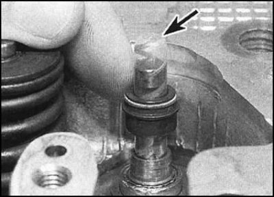
3. Lubricate the valve stem seals with clean engine oil and install them on the guide bushings (skoda branded caps are equipped with special plastic protectors, which are used when putting the cap on the valve).
4. After placing the cap on the stem, place it on the guide sleeve. Try not to damage the cap lips as you lower it along the valve stem.
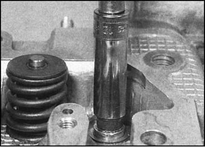
5. Using a socket head of the appropriate size or a piece of pipe of the appropriate diameter as a mandrel, press the cap tightly onto the sleeve. If used, remove the plastic protector from the end of the valve stem.
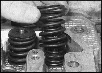
6. Place the inner and outer springs on your saddles),...
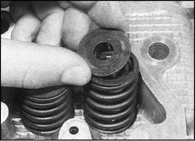
...put the retainer plate on top.
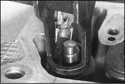
7. Using a special tool, compress the valve springs and seat the split lock crackers in the groove on the rod.
Note: A small amount of grease applied to the inside of the crackers will help temporarily hold them in place until the tool is released. Release the tool and repeat the procedure for the remaining valves.
8. Once all valves are installed, place the head on the workbench and tap it with a hammer through a wooden block to seat the components.
9. Install the head on the cylinder block (see Part Repair without removing a 1.3 l petrol engine from a car of this Chapter).
Assembly - 1.6 l and diesel engines
Attention! When using old components, they must be installed on the engine strictly in the same order. This condition also comes into force after finishing the grinding of new valves - they must be installed in the head strictly in the same seats to which they were ground.
1. On diesel engines, if removed, seat the swirl chambers perpendicularly into their sockets using hammer blows through a wooden block. Pay attention to the presence of guide grooves in the sockets.
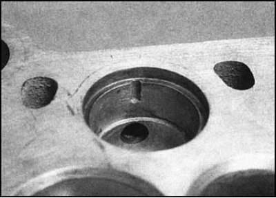
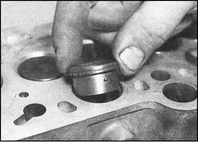
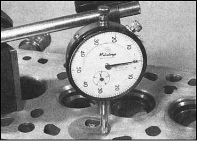
2. Using a dial gauge, determine the amount of protrusion of the swirl chambers above the head surface. If the measurement results exceed the specified Specifications acceptable value, special mechanical treatment of the head should be carried out in a car service workshop in order to prevent the risk of damage to the chambers as a result of contact with the pistons.
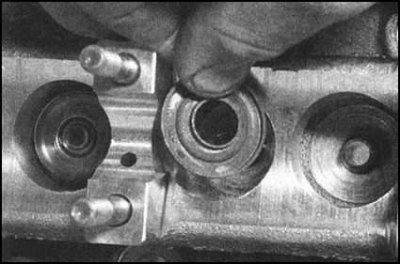
3. Turn the head over and rest it on a couple of wooden blocks. Where required, install the lower spring seats first with the convex side facing the head.
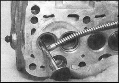
4. Lubricating the valve stems with clean engine oil,...
...install them one by one into the corresponding guide bushings. Put a special plastic protector on the end of the stem of the first valve.
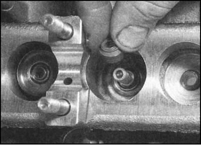
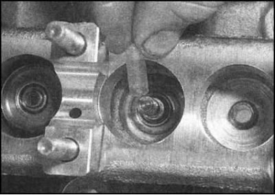
5. Dip the oil deflector cap into clean engine oil and, placing it on the rod,...
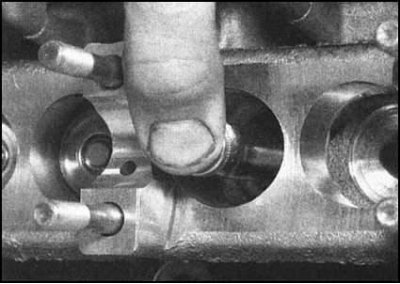
...fit tightly onto the guide bushing. Use a deep socket of the appropriate size as a mandrel.

6. Place the spring on the valve stem.
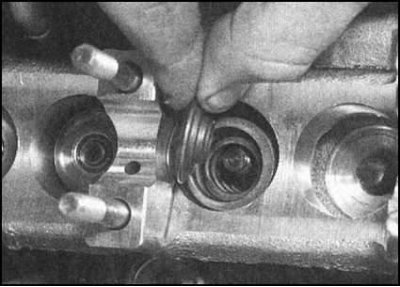
7. Place the upper seat on top of the spring...
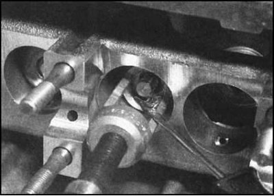
...then compress the assembly with a special tool and install it into the groove on the split lock rod.
8. Repeat the procedure for the remaining valves. To seat the components, tap the ends of the valve stems with a soft-faced hammer, then make sure the upper spring seats are securely held with crackers.
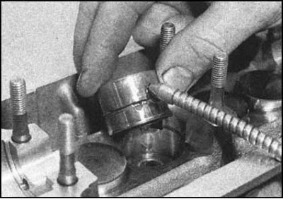
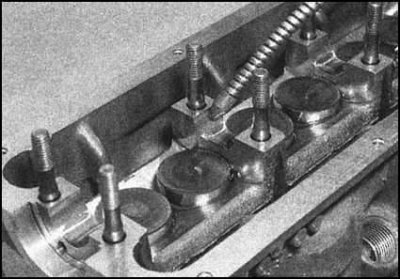
9. Lightly lubricate the walls of the hydraulic tappets with clean engine oil and install them in their sockets in the head. Push the tappets into the sockets until they stop against the valve stems, then lubricate the surfaces that contact the camshaft lobes.
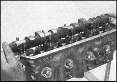
10. Lubricate the crankshaft journals and bearing surfaces in the head with clean engine oil, then carefully place the shaft in its original place. Hold the shaft firmly by the ends and try not to damage its journals and cams.
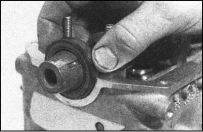
11. On diesel models, lubricate the lips of the new seal with clean engine oil and slide it onto the crankshaft journal. Sliding the seal along the journal, seat it into the lower half of its housing in the head (see section Repair without removing a diesel engine from a vehicle).
12. Lubricate the top of the camshaft journals and install the bearing caps on them.
Petrol engines 1.6 l
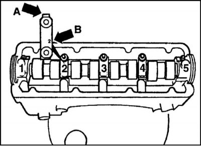
1. Make sure the camshaft bearing caps are oriented correctly. The caps should be facing the wider casting projections toward the intake side of the head. The identification markings should be legible when looking at the head from the exhaust side.
2. Install the 2nd and 4th bearing caps in their places and tighten their fastening nuts in a diagonal order with the first stage force.
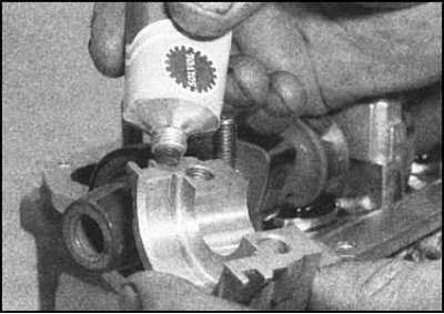
3. Lubricate the mating surfaces of the 1st and 5th bearing caps with sealant. Install the 1st, 3rd and 5th caps in their places and tighten the fastening nuts with the force of the 1st stage.
4. Working diagonally, tighten the fasteners of all covers to the second stage tightening angle (use a protractor or a specially made template made of thick cardboard).
5. Screw in the 5th bearing cover mounting bolts and tighten them to the required torque.
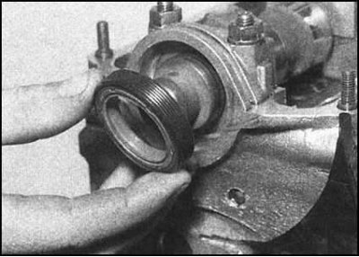
6. Lubricate the lips of the new seal with clean engine oil and place it on the camshaft journal. Using a deep socket of the appropriate size as a drift, tap the seal perpendicularly into the seat in the housing until it rests against the internal stop (see section Repair without removing a 1.6L petrol engine from a car of this Chapter).
7. Reinstall the thermostat housing and engine oil pressure switch.
Diesel engines
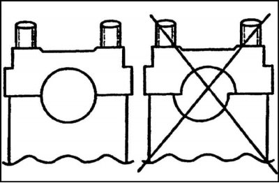
1. The mounting holes are drilled in the covers asymmetrically, which ensures the unambiguous installation of the latter.
2. When installing the bearing caps, the camshaft must be turned with the working projections of the cams of the valves of the first cylinder facing up.
3. Install the 2nd and 4th bearing caps and tighten them evenly in a diagonal order to the required torque.
4. Now install the 1st, 3rd and 5th bearing caps. Tighten the mounting nuts to the required torque, then check that the 5th bearing cap is seated correctly by lightly tapping the end of the camshaft.
5. Install the cooling tract pipe, replacing its gasket/sealing ring if necessary.
6. Reinstall the fuel injection nozzles and glow plugs.
All engines
1. In accordance with the instructions given in Parts Repair without removing a 1.6L petrol engine from a car, Repair without removing a diesel engine from a vehicle of this Chapter, perform the following procedures:
- a) Install the camshaft gear in place;
- b) Install the intake manifold and exhaust manifold with new gaskets.
2. Install the head on the cylinder block (see Part Repair without removing a 1.6L petrol engine from a car or Repair without removing a diesel engine from a vehicle of this Chapter).