
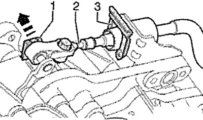
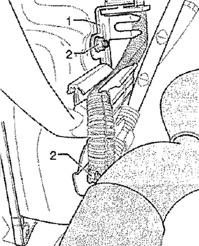
Note: The lock washer of the selector lever cable -3- and the lock washer -1- must be replaced. Do not bend or break the selector lever cable. When removing the gearbox, the selector lever cable is removed from the cable support.
If the lock washer cannot be removed without damaging the selector lever cable, it is also possible to remove the cable support from the gearbox -2- (remove screws -1-). Touch your hand (without gloves) to ground to remove the electrostatic charge.
Unlock connector -1- by turning it to the left and disconnect connector from mechatronic unit.
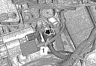
Carefully! Never touch the plug-in contacts in the gearbox connector with your hands. so that static discharge does not damage the computer and mechatronics.
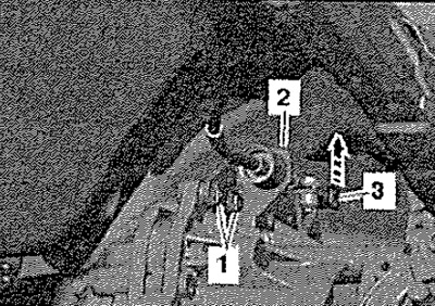
Disconnect connector -3- for starter solenoid -2-. Roll back the protective cover and unscrew the nut -4- of the connecting wire on the solenoid relay. Disconnect the ground wire from the lower starter mounting screw. Remove screw -1- and remove starter.
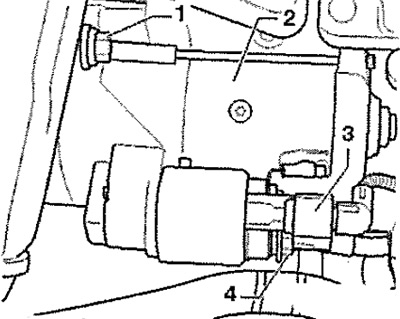
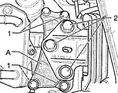
Release all engine/gearbox connecting screws -1, 2 and 4- accessible from above. To do this, if necessary, use nozzle -T10035-.
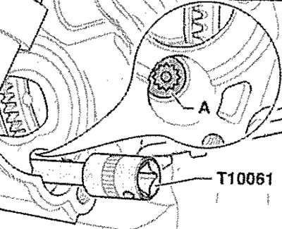
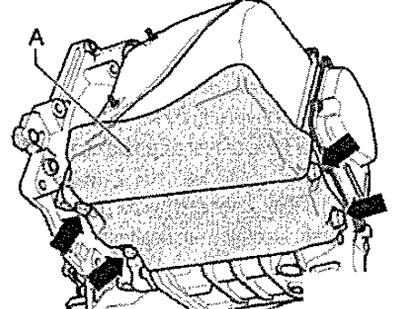
Note: Tighten screws -3 and 5- securing starter to gearbox. Bolt -pos. 4-, marked with the letter -A- in the figure, is located in the hole for the starter and is accessible only after the starter has been removed. Unscrew this screw using the XZN 14 socket -T10061-. When the expansion tank is opened, hot steam escapes. Cover the lid with a cloth and carefully open the tank.
When the engine is warm, the cooling system is under pressure. Before disconnecting the coolant hose, turn expansion tank cap slowly to release pressure first. Place a lint-free rag on the transmission oil cooler and gearbox to catch any leaking coolant. Mark the coolant hoses to the transmission oil cooler to prevent misconnection during installation.
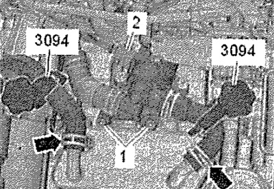
Disconnect connector -2-. Release screws -1- and detach gearbox coolant valve -N488-. Clamp the coolant hoses with hose clamps -MP7-602 (3094) -. Open hose clamps -arrows- and detach hoses from transmission oil cooler. Close the transmission oil cooler openings with clean plugs. Remove the caps on the threaded connections of the cups of the front suspension struts.
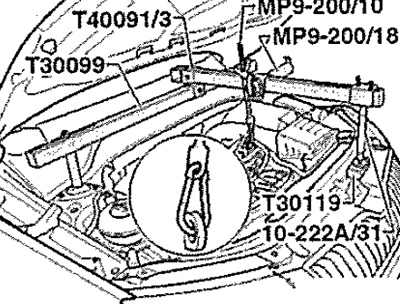
Fit retaining device -T30099- together with other components as shown in illustration. Lightly tension the engine/gearbox assembly on the hooks, but do not lift. Loosen the front wheel bolts. Raise a / m. Dismantle the front wheels. Remove the lower soundproofing casing of the engine.
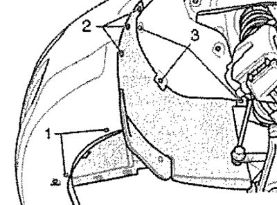
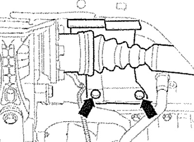
Release screws -1 - to -3- and remove cover assembly.
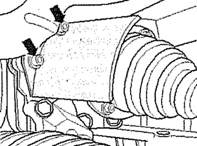
Unscrew the nuts -2- of the bracket -1- on the oil sump and remove the bracket from the studs.
Note: The studs are welded to the oil sump at the front of the gearbox. Unscrew the bottom nut from below after removing the noise insulation.
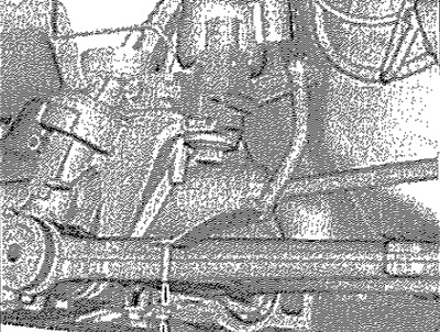
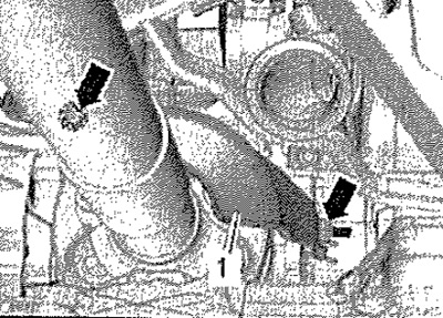
If present, remove lower protective cover -A-gearbox -see. arrows-. Disconnect the exhaust system at the coupler and remove the exhaust system bracket from the attachment bracket. Tie up the exhaust pipe.
Note: The bellows at the front of the exhaust system must not be bent more than 10°, risk of damage.
Disconnect the connector at the wire connector between the attachment bracket and the engine, and set aside. If present, remove front left vehicle level sender -G78-. Lock attachment bracket before removing.
Note: If the attachment bracket does not lock, then the running gear must be measured later.
Vehicles with front wheel drive
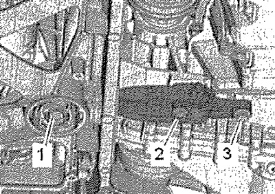
Remove stabilizer bar support, to do this unscrew screws -1, 2 and 3-. Lower the attachment bracket to the maintenance position.
Detach right drive shaft shield from engine -arrows- (in the presence of).
Vehicles with all-wheel drive
Detach the lower support of the power unit from the gearbox by unscrewing the bolts -2 and 3-. Remove attachment bracket. Unscrew nuts -arrows- and remove heat shield for right driveshaft (in the presence of).
Further for all vehicles
Remove the left and right drive shafts from the gearbox flange shafts. Tie up the right drive shaft as high as possible and move the left drive shaft back and secure (without damaging the protective coating).
Note: Do not damage the protective coating on the drive shafts.
Vehicles with front wheel drive
Remove the right flange shaft.
Vehicles with all-wheel drive
Release screws -1 and 2- and remove bracket for bevel gear.
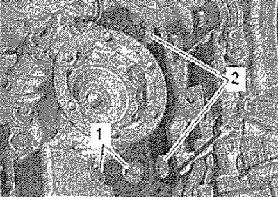
Release screws -arrows- and remove heat shield -1-.
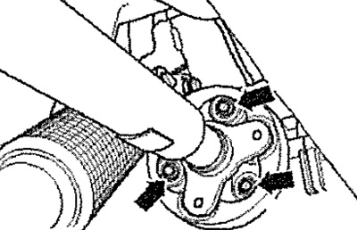
For subsequent installation, mark the relative position of the elastic coupling and the flange of the angular drive. Unscrew the propshaft from the bevel gear -arrows-, holding it at the triangular flange with a lever.
Slightly press the engine/gearbox assembly forward (to the front of the body) and disconnect the cardan shaft from the angular transmission.
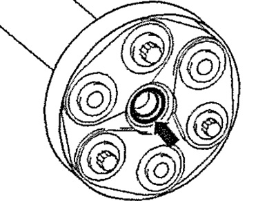
Carefully! Risk of damage to O-ring arrow - propshaft flange. Keeping the shaft parallel to the floor, press it as far back and to the right as possible (to the right side of the vehicle). If the O-ring is damaged, the cardan shaft must be replaced.
Further for all vehicles
Remove screws -1- and -2-. Remove console -A-.
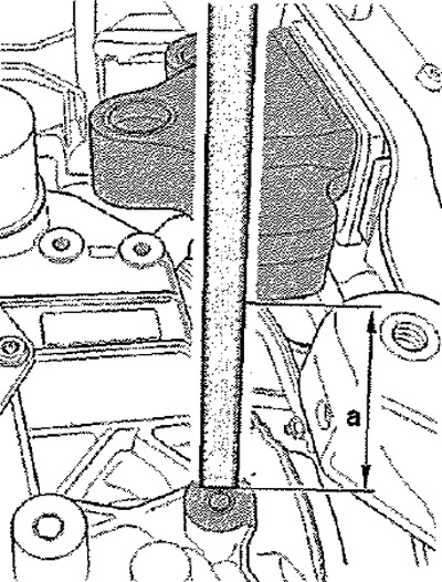
Then lower on the hooks of the holding device -MP9-200 (10 -222 A) - the engine and gearbox so that there is a gap of dimension -a- between the gearbox bracket and the gearbox support. Size -a- = approx. 70 mm. Position gearbox support -3282- on engine and gearbox jack -VAG 1383 A-.
Align gearbox mounting brackets with holes in adjustment plate -3282/42A-. Screw on the fasteners as shown on the adjustment plate -3282/42A-. Position engine and gearbox jack -VAG 1383 A- under vehicle. Upper arrow on adjusting plate -3282/42- points in direction of travel. Align gearbox mounting -3282- parallel to gearbox. Screw pin -3282/29- into gearbox. Fasten both mounting elements to the gearbox as shown in the figure.
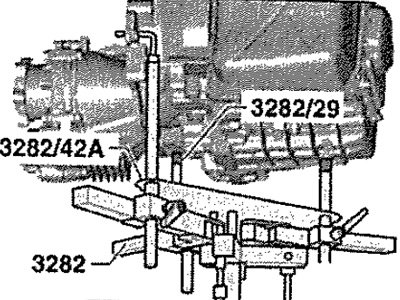
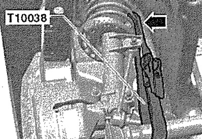
Secure gearbox with lashing strap -T10038- to gearbox bracket -3282-.
Note: The illustration shows the automatic gearbox DSG -009 for "all-wheel drive vehicle". fastening elements for vehicles "front wheel drive" are identical.
Support gearbox with engine and gearbox jack -VAG 1383 A-. Release remaining connecting screws -6... 10- for engine/gearbox. Press gearbox off balance bushings -A-. Move the gearbox slightly away from the engine. Lower gearbox slightly using engine and gearbox jack -VAG 1383 A-. When lowering the gearbox, change the mounting position of the gearbox 3282- using the spindles. When lowering the gearbox, withdraw the gear selector cable from the cable support.
Note: Keep an eye on all coolant lines and hoses when lowering the gearbox. Do not bend or break the selector lever cable.
Move the gearbox and fix it on the mounting stand.