
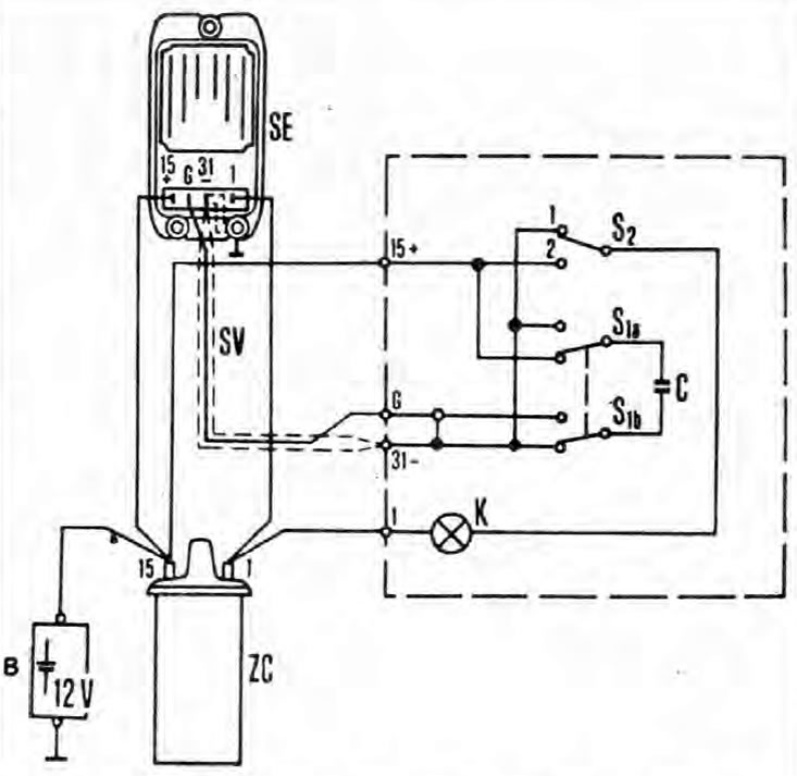
Figure 5.5. Connection diagram of the block for checking the ignition system
B - Vehicle battery; C - Capacitor (2 microfarads); K - Control lamp (12 V, 2 W); S1 - Pushbutton switch (twin, 2-position); S2 - Switch (single, 2 position); SE - Control unit; SV - Screened wire; ZC - Ignition coil
Note: Please refer to the warning in the Chapter 1. Always turn the ignition off before disconnecting or connecting any component and when using a multimeter to check resistance
General provisions
1. The components of non-contact ignition systems are usually very reliable. Faults are most often caused by loose or dirty connections, or high voltage burnt traces due to dirt, moisture, or damaged insulation. Always thoroughly check all wiring and eliminate all possible causes of malfunction before jumping to conclusions about the failure of any individual component of the ignition system.
2. When checking the ignition spark, hold the end of the high voltage wire to be tested at a distance of 10 mm from the engine.
3. Make sure that the ignition coil does not idle (those. without load in the form of a distributor or something else with a suitable resistance), otherwise the control unit may be damaged. It is necessary to create a spark gap, as just described, or to ground the high voltage wire of the ignition coil.
4. Do not attempt to diagnose misfiring by removing one high voltage wire at a time. There is a risk of electric shock and damage to the insulation.
Engine won't start
Preliminary checks
5. If the engine does not turn at all, or turns very slowly, check the battery and starter. Connect a voltmeter across the battery terminals (observe polarity). Disconnect the ignition coil high voltage wire from the distributor cap and ground it, then note that the voltage is measured by cranking the engine with the starter for no more than ten seconds. If the result is less than 9.5 volts, check the battery, starter and charging system.
6. If the engine cranks at normal speed but does not start, check the secondary circuit. Attach a stroboscope (according to the manufacturer's instructions) and turn the engine over with the starter. If flashes are observed, then voltage is reaching the spark plugs, so check them first. If there are no flashes, check the high voltage wires, then the distributor cap, carbon brush and distributor slider (Section 1, And Chapter 2 from this Section).
7. If there is an ignition spark, check the fuel system (Section 4).
8. If there is still no ignition spark, check the voltage at the clamp "+" ignition coils (black and orange wires); it should be equal to the battery voltage (i.e. at least 11.7 volts) If the voltage drop between the battery and the ignition coil is greater than 1 volt, check the wiring connection from the ignition switch to the battery and its ground until you find the problem.
9. If the power to the ignition coil is normal, check the primary winding of the coil (and possibly secondary) as described in Chapter 4. Replace the ignition coil if it is defective, but first carefully check the condition of the primary circuit connections.
10. If the ignition coil is in order, the ignition control unit or the impulse winding of the distributor is probably faulty. For a quick test, connect a low wattage lamp to the primary terminals of the ignition coil. If the lamp flashes when the engine is cranked, then most likely the starter, control unit and distributor are working.
11. If the control unit and distributor are normal, the primary circuit is in order, then the fault is in the components of the secondary circuit. Check them carefully as described above.
12. If the test lamp does not flash, the fault is either in the distributor pulse winding or in the ignition control unit. Further verification can be done as follows.
Specific Checks
13. Make a block for testing the ignition system (see fig. 5.5).
14. Disconnect the high voltage wire from the distributor cap. Position the end of the wire approximately 10mm from the engine, or connect it to an ignition spark air gap tester.
15. Disconnect the wiring connecting the distributor to the control box. Connect the ignition test box to the control box as shown and turn on the ignition.
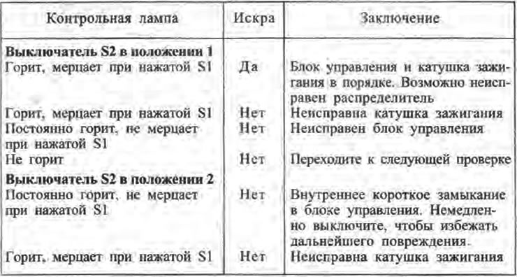
16. The test is carried out with switch S2, first in one position, then in another. In each position, a reaction is observed when the switch S1 is pressed several times, this simulates the switching of the input from the distributor. Observe the test lamp in the test block and the spark gap. Possible results and sequence of actions are given in the table below.
17. If after the above checks it is revealed that the control unit and the ignition coil are working correctly, measure the resistance of the distributor pulse winding. If resistance does not correspond to the data resulted in Specifications, replace the distributor.
Misfire
18. Irregular misfires are possible due to a loose connection or broken wire in the low voltage circuit, or due to a malfunction in the distributor runner on the ignition coil side.
19. With the ignition off, carefully check the entire system. If possible, check the primary circuit as described above.
20. Make sure the ignition coil, distributor cap and high voltage wires are clean and dry. Check wires and spark plugs (replacement if necessary), then check the distributor cap, carbon cheek and distributor slider (Section 1).
21. Regular misfiring is most likely due to a fault in the distributor cap, high voltage wires or spark plugs. Using a stroboscope as described above, check for high voltage on the wires.
22. If there is no high voltage on one wire, the fault will be in that wire or in the distributor cap. If there is voltage on the wires, the fault will be in the spark plugs; check and replace them if in doubt.
23. If there is no high voltage, check the ignition coil; its secondary winding may collapse under load.