



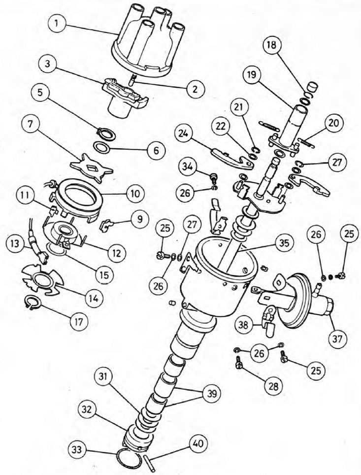
Pic. 5.2. Ignition distributor and its components
1. Distributor cover; 2. Carbon contact; 3. Slider distributor; 5. Retaining ring; 6. Spring washer; 7. Impulsor; 9. Special nut; 10. Pulse winding; 11. Special nut; 12. Rotating plate; 13. Terminal; 14. Base plate; 15. Washer (0.5, 0.1 or 0.16 mm); 17. Retaining ring; 18. Fixing spring; 19. Runner bushing; 20. Spring; 21. Retaining ring; 22. Washer; 24. Weight; 25. Screw; 26. Spring washers; 27. Flat washer; 28. Screw; 31. Washers; 32. Clutch; 33. Fixing spring; 34. Screw; 35. Shaft; 37. Vacuum chamber; 38. Spring clip; 39. Bushings.
Removing
1. Disconnect the negative cable from the battery.
2. Mark the location of the high voltage wires, then separate them from the spark plugs. If possible, do not separate the wires from the distributor cap.
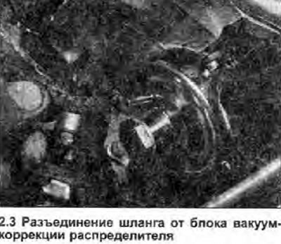
3. Disconnect the vacuum tube from the advance block (see illustration).
4. Release the mounting brackets, separate the distributor cover and move it to the side.
5. Slide the rubber cover back off the ignition control box (attached to the inner panel of the right wing). Note the connections, then separate the two low voltage wires from the terminals in the control box.
6. Set engine to TDC, cylinder #1 on compression stroke. See Section 2.
7. The distributor can be removed together with the extension tube, or separately. The latter method is preferred. when the distributor is to be rebuilt.
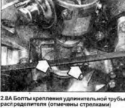
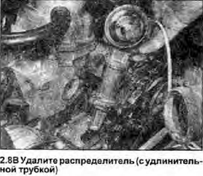
8. To remove the distributor together with the extension tube, unscrew the two bolts securing the tube flange to the actuator cover, then remove the distributor and tube (see illustrations).
 |  |
9. When removing the distributor and pipe, the slider will turn when the shaft gear disengages from the helical drive gear on the camshaft. Note the end position of the slider so you can position it the same way when you install it.
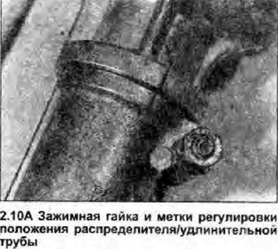
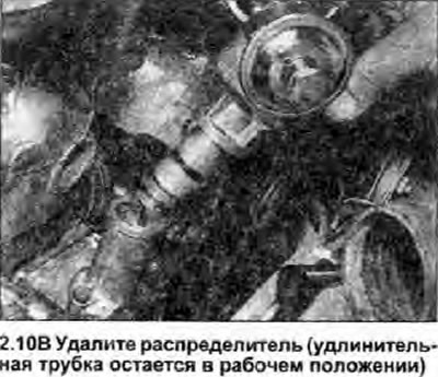
10. Before separating the distributor from the pipe, first mark their relative positions. Then loosen the clamping nut and bolt, and remove the distributor (see illustrations).
 |  |
11. Do not rotate the crankshaft without a distributor, nor rotate the distributor shaft.
12. Remove the O-ring from the groove in the distributor; it must be replaced.
Bulkhead
13. Get the distributor slider.
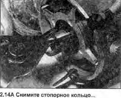
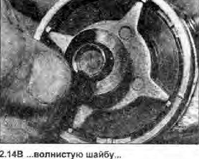
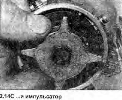
14. Release the retaining ring and remove the wave spring washer and impulsator (see illustrations).
 |  |
 |
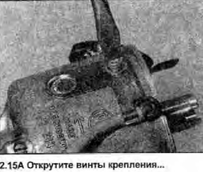
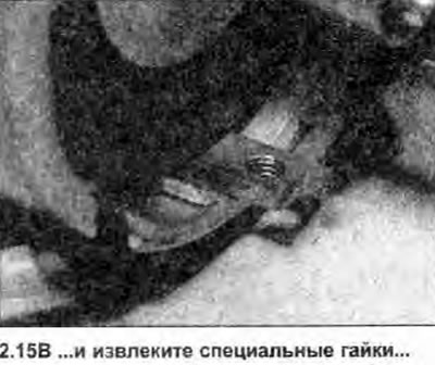
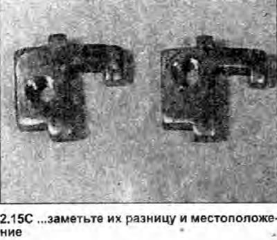
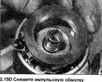
15. Remove the fastening screws from the distributor housing. Note the positions of the mounting brackets and special nuts. Remove the screws, remove the nuts, and lift the pulsator coil (see illustrations).
 |  |
 |  |
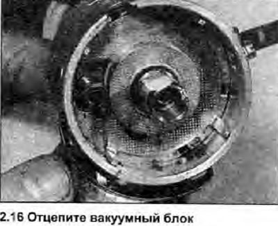
16. Removes the vacuum block (see illustration).
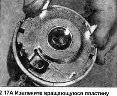
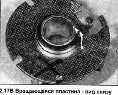
17. Remove the rotating plate (see illustrations).
 |  |
18. Check up an axial backlash of a shaft of the distributor. If required, the distributor can be disassembled further as follows.
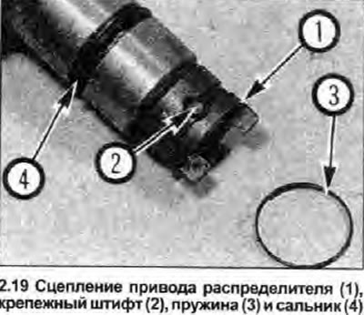
19. Remove the spring from the distributor drive clutch, then using a marking tool, apply alignment marks to the clutch and shaft. It is important that the clutch is installed correctly in relation to the distributor slider. Release the distributor shaft by pressing out the mounting pin and removing the clutch (see illustration); note the thrust washer.
20. Get a shaft, having noted persistent washers under assembly of a centrifugal regulator of an advancing of ignition.
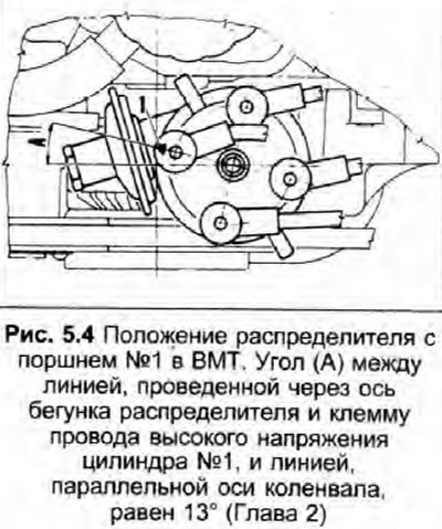
21. Clean and lubricate the ignition timing weights and springs. Replace springs (if possible).
22. Clean and inspect all components and replace as needed. If a large number of parts are worn out, then it would be more correct to replace the distributor.
23. Clean and inspect the distributor cap. If there are cracks or other damage, the cover must be replaced. Use an ohmmeter to check that there is no continuity between the terminal segments in the cover. Similarly, make sure that there is no conduction between the body of the distributor slider and its copper tip; note that the slider has an internal resistance to suppress radio interference.
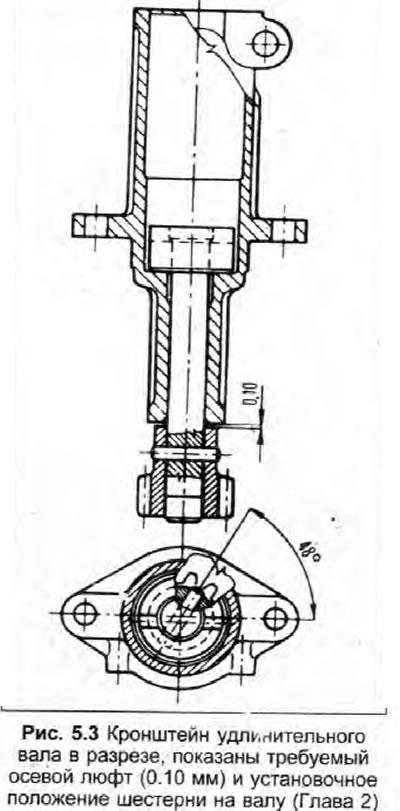
24. If the distributor extension tube has been removed, inspect it, shaft and satellite for signs of wear. Insert a feeler gauge between the base of the bracket and the top of the drive gear. Ideally, the axial play of the shaft in the bracket should be 0.10 mm (see fig. 5.3). Although it is possible to replace the shaft and gear, it is best to have this work done by a Skoda dealer.
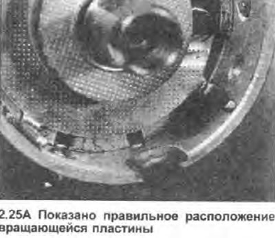
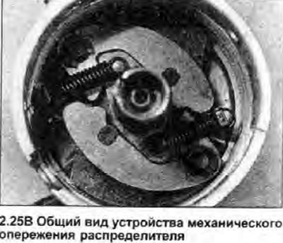
25. Assembly is carried out in the reverse order of removal, paying attention to the following (see illustrations):
- a) When installing the rotating plate, position it so that the groove is aligned with the protrusion on the inside wall of the distributor housing.
- b) Apply a few drops of oil to the pivot shafts and springs of the advance assembly, shaft surfaces and bearings.
- c) According to the marks made during removal, correctly position the clutch on the end of the shaft (in relation to the distributor slider), then make sure the spring fixes the ends of the pin.
- d) Before connecting the vacuum capsule, lightly lubricate its lever.
- e) Make sure the mounting plates are correctly positioned as noted during removal.
- f) Replace the O-ring in the groove in the distributor housing, and lubricate it with engine oil to ease installation.
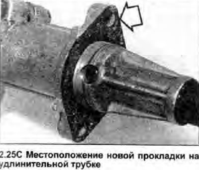
- g) Install a new gasket on the back of the extension tube flange (if it was removed).
 |  |
 |
Installation of the old distributor
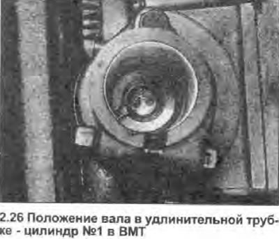
26. First make sure the #1 cylinder piston is at TDC. Rotate the distributor shaft to align the tip of the slider with the notch on the distributor housing. If the extension tube is installed on the engine, make sure that the distributor drive lug is aligned with the engagement groove on the shaft (see illustration). If installing a distributor with an extension tube, place the distributor slider in the preset position as noted during removal.
 |  |
27. Establish the distributor, being guided by labels. If necessary, rotate the gel spreader slider slightly to engage the drive lug or gear teeth. Insert the mounting bolts and tighten them with the tightening force specified specifications.
28. Install the distributor cap, then connect the high voltage wires (Section 1).
29. Connect the vacuum tube and low voltage wiring from the distributor to the ignition control unit.
30. Check ignition timing, and adjust if necessary (Section 1).
Installation of a new distributor
31. If a new distributor is installed (or if no marks were made before removal), the procedure is basically the same as that already described. If you position the distributor so that the tip of the slider aligns with the notch on the distributor housing when the engine is at TDC, the initial setting will already be accurate enough to start the engine. The ignition timing can then be checked and adjusted as described in Section 1.