



Crankshaft assembly - general information
The crankshaft is forged from steel. The shaft has three main and four connecting rod journals. The cranks with connecting rod journals of the first and second cylinders are located between the first and second main journals of the shaft; between the second and third main journals are located the crankpins of the third and fourth connecting rod journals.
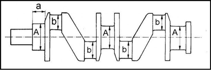
a - Width of main journal; b - Ø of connecting rod journal; A - Ø of the main journal
In order to reduce the load on the main bearings, the cranks are equipped with forged counterweights that balance the centrifugal forces arising between two adjacent supports.
All crankshaft cranks and journals are equipped with internal oil passages through which oil is supplied to the bearing shells.
The cranks themselves are not subject to processing. As for the journals and both crankshaft journals, they are carefully processed. Both the main and connecting rod journals are subjected to surface hardening with high-frequency current. The diameter of the main journals is 60 mm, connecting rod - 45 mm.
The end face of the rear crankshaft journal is equipped with a flange for mounting the flywheel. Sealing of the rear journal in the block is achieved using an 85x105x12 mm oil seal.
(Article published on the website: www.skodabook.ru)
The front journal of the shaft is a neck used for mounting the toothed wheel/sprocket of the belt/chain drive of the camshaft, as well as the V-belt pulley of the auxiliary drive (water pump and generator). The sealing of the front journal fit is ensured by the front oil seal (42x58x8 mm).
Both seals are made of fluororubber and are characterized by increased reliability and durability.
The amount of axial play of the shaft is controlled by installing special spacer rings and a thrust washer, which are installed on the first main journal of the shaft. The spacer rings are locked from turning by a projection provided on the outer side. The permissible amount of axial play of the crankshaft is presented in the Specifications at the beginning of this Chapter.
In addition to the nominal thickness (1.480÷1.490 mm), thrust rings are also produced in repair sizes: 1.605÷1.615 mm, 1.703÷1.740 mm and 1.855÷1.865 mm.
Larger rings should always be installed on the ground side of the crank cheek. The nominal size ring should always be installed on the thrust washer side.
In case of wear, the thrust washer (loss of smoothness of the side surfaces) subject to replacement.
All crankshafts undergo static and dynamic balancing at production with an accuracy of up to 0.2 Nm.
The crankshaft main bearing caps are made of cast iron and are attached to the cylinder block using double-ended M11 bolts. The caps are marked with the numbers "1", "2" or "3". The cap with the number "1" should be installed on the bearing closest to the timing drive, the one with the number "3" - on the one closest to the flywheel, and the one with the number "2" - on the middle one.
The crankshaft bearing shells are made of a thin steel strip coated on the inside with a layer of a special alloy. The layer thickness is 0.35 mm. The main bearings are 24 mm wide with a thickness of 2.5 mm, and the connecting rod bearings are 22 m with a thickness of 1.5 mm.
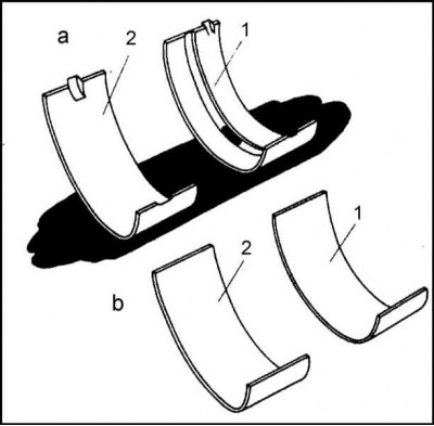
a - Main bearings; b - Connecting rod bearings; 1 - Upper liners; 2 - Lower liners
Along the entire length of each of the upper main bearings there is a groove, which serves to supply motor oil, entering through an oval-shaped hole in the bearing. The end surfaces of the bearing half-rings are equipped with locks, which ensure the uniqueness of the half-rings' fit and fixation from turning.
The connecting rod bearings have a smooth surface and are not equipped with locks.
There is no marking on the inserts, and therefore their thickness is determined using a micrometer.
The liners remain suitable for further use if they are not too worn, do not leave excessive bearing clearance, are free of cracks, scratches and chips in the surface layer. Defective liners must be replaced without fail. The authors of this Manual recommend replacing the liners as a set for all bearings at the same time.
Before checking the condition of the crankshaft, it must be cleaned of grease and dirt. If obvious defects are detected, or if there is no confidence in the assessment of the condition of the shaft, it must be replaced. Upon completion of any type of restoration repair, it is necessary to thoroughly clean all oil flows of the shaft. (first use kerosene, then blow out the holes with compressed air).
Removal
1. Remove the cylinder head, timing chain and sprockets (see Part Repair without removing a 1.3 l petrol engine from a car of this Chapter). Secure the cylinder liners.
2. Remove the connecting rod caps from the crankshaft. If necessary, remove the connecting rod assemblies (see section Removal, condition check and installation of connecting rod and piston assemblies).
3. Before you begin removing the crankshaft, do the following:
- a) Temporarily place the outer thrust washer on the shaft journal (oil flow grooves outward from the bearing cap), align the stop flag with the groove on the cover and seat the washer until it stops in its socket. Make sure that the flag of the inner thrust washer also enters the corresponding groove in its cover;
- b) After installing the thrust washer, fit the large spacer sleeve (with the beveled inner edge facing the block), adjusting washer, segment key (with the beveled side facing inward) and the timing chain sprocket;
- c) Install the crankshaft pulley, screw in the pulley bolt (don't forget the puck) and tighten it to the required torque, taking appropriate measures to prevent the shaft from turning (see section Removal, condition check and installation of the flywheel). Note that incorrect installation of thrust washers will cause the shaft to jam when tightening the pulley bolt. As a result of such jamming, the washers themselves can easily be damaged.
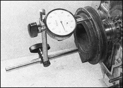
4. Using a plunger-type dial gauge, measure the crankshaft axial play. Secure the gauge so that its plunger rests against the end of the front journal of the shaft and is parallel to the axis of the latter. Move the shaft back as far as it will go, reset the gauge to zero, then push the shaft forward over its full stroke and read the gauge reading. Compare the result with the Specifications. The amount of axial play is adjusted by selecting a thrust washer.
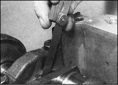
5. Alternatively, the shaft axial play can be measured using a blade-type feeler gauge. Move the shaft to the end of its stroke toward the flywheel, then use the feeler gauge to measure the gap between the first crank cheek and the thrust washer.
6. Remove all temporarily installed components. Also remove the flywheel (see section Removal, condition check and installation of the flywheel).
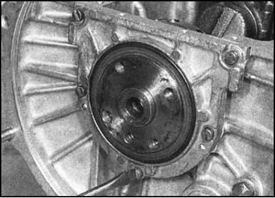
7. Remove the mounting screws and remove the rear oil seal housing assembly from the shaft journal. Remove the housing gasket (if such is provided). During assembly, the gasket must be replaced without fail.
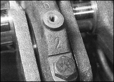
8. Check the main bearing caps for identification markings. The markings are usually represented by marks in the form of numbers from 1 to 3, counting from the pulley side. If there is no marking, apply it yourself (use a center punch, as you did when marking the connecting rod caps).
Note: In addition to the cover number, the location of the marks must clearly indicate the installation direction of the covers.
9. Unscrew the mounting bolts and remove the main bearing caps together with the liners.
10. Remove the crankshaft and remove the thrust washer from its right journal. Try to remember the installation position of the washer.
11. Remove the upper main bearing shells from their beds and stack them together with the lower ones, in the order of installation on the engine.
1.6L and diesel engines
Note. If no work is planned to restore the connecting rod and piston assemblies, there is no need to remove the head and pistons. It will be enough to simply move the pistons up the cylinders, removing the lower connecting rod heads from the crankshaft journals. It is recommended to perform the work on a mounting stand.
1. In accordance with the instructions given in Part Repair without removing a 1.6L petrol engine from a car or Repair without removing a diesel engine from a vehicle of this Chapter, perform the following procedures:
- a) Remove the timing belt drive gear from the crankshaft;
- b) Remove the clutch assembly components and flywheel;
- c) Remove the oil pan, oil deflector (if provided) and an oil pump with an oil intake;
- d) Remove the front and rear oil seal housing assemblies.
2. If necessary, remove the pistons with connecting rods (see section Removal, condition check and installation of connecting rod and piston assemblies).
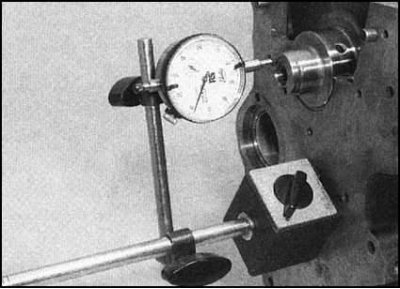
3. Using the same procedure as for the 1.3L engine, measure the crankshaft axial clearance. The axial clearance is adjusted by adjusting the thickness of the thrust washers.
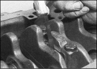
4. Alternatively, the clearance can be determined using a blade-type feeler gauge, measuring the maximum clearance between the cheek of the 2nd crank and the thrust washer. Compare the result with the requirements of the Specifications.
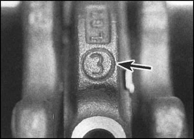
5. Check the main bearing caps for factory markings. The digital marks are applied in the order of the caps in the direction from the timing drive to the flywheel.
6. In several stages (1/4 turn per set) loosen the cap mounting bolts, then remove them by hand. Lightly tap with a soft-faced hammer to remove the caps together and the liners. Tape the liners to their caps.
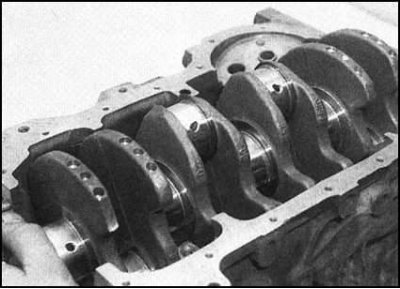
7. Carefully remove the crankshaft. Try not to let the upper main bearing shells fall out. Since the shaft weighs quite a lot, it would be wise to use an assistant. Place the removed shaft on a flat work surface, supporting it with wooden wedges.
8. Remove the upper bearing shells and stack them together with the lower ones in the order of installation on the engine. Remove the thrust washers installed on both sides of the 3rd crank.
9. Pay attention to the recesses machined in the covers and block - these recesses are designed to accommodate the protrusions of the liners and determine the unambiguous installation of the latter.
Examination
1. Thoroughly wash the crankshaft with solvent and dry it. Wash the oil passage holes and make sure they are clear (use a special brush). To avoid damaging the new liners, chamfer the edges of the holes.
2. Check the condition of the main and connecting rod journals of the shaft. If signs of uneven wear, scoring, cracks, cavities and other damage are detected, the shaft should be given a turning with subsequent replacement of the bearings with repair ones.
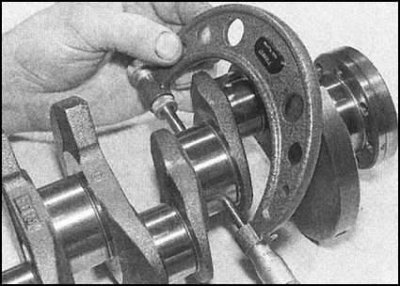
3. Using a micrometer, measure the diameters of the main and connecting rod journals of the shaft. By measuring the diameter at various points on the journals, check the latter for signs of ovality or taper. Compare the results of the check with the requirements of the Specifications; if necessary, regrind the shaft.
4. Check the condition of the surfaces of both shaft journals that contact the seals. If you find any scoring, roughness or other damage that could lead to the failure of the new seal, you should seek help from a car service specialist, where the appropriate restoration repair of the journals can be performed.
5. Using a plunger-type dial gauge, determine the lateral runout of the crankshaft in its middle section. The shaft should be placed in V-shaped blocks. Try not to damage the surfaces of the journals and journals of the shaft during the check. The maximum permissible value of the lateral runout of the crankshaft is not specified by the manufacturers, but the authors of this Manual recommend taking a value of 0.05 mm as a starting point. If this value is exceeded, the shaft should be replaced or delivered to a car service workshop for restoration.
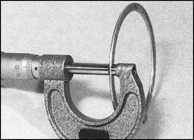
6. On 1.3 l engines, it is necessary to determine the thickness of the thrust washers with a micrometer. Worn washers are replaced in pairs from those corresponding to them in the size group. If the shaft was subjected to turning, one of the washers after selection may be thicker than the other, and should be installed on the inner side (close to the crank cheek).
7. For a description of the procedures for checking the condition of the main and connecting rod bearing shells, see Section Checking the condition and selecting the liners of the main and connecting rod bearings of the crankshaft.