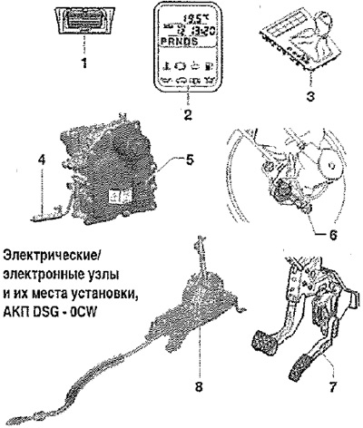
1. Diagnostic socket: Fitting location: Driver's footwell trim
2. Gear selector position indicator -Y6-: Fitting location: Integrated in the instrument panel; an off gear indicator indicates an emergency run with an inactive TCM; A fully lit gear indicator indicates an emergency run with the TEC ECU active; can only be replaced together with the instrument panel insert
3. Trim for selector mechanism with gear selector illumination lamp -L101-. The gear selector illumination lamp -L101- is integrated in the gear selector cover. Gear selector illumination lamp -L101- checked by self-diagnosis
4. Sensor for gearbox primary torque -G182-: checked via self-diagnosis; is part of the mechatronics for the double clutch gearbox -J743-
5. Mechatronic unit for double clutch gearbox -J743-: Checked using self-diagnosis
6. Brake light switch -F- and brake pedal switch -F47-: Signal transmission from engine control unit to gearbox control unit via CAN bus; checked by self-diagnosis
7. Accelerator pedal position sender -F8-: Transmission of signals from the engine control unit to the gearbox control unit via the CAN bus; checked by self-diagnosis
8. Selector mechanism: Selector lever -E313- with tiptronic switch -F189-, selector lever sensor control unit -J587-, selector lever lock switch in P position -F319- and selector lever lock magnet -N110-; checked by self-diagnosis; these nodes cannot be replaced separately; Removal and installation is possible only together with the switching mechanism
Mechatronic unit for double clutch gearbox -J743-
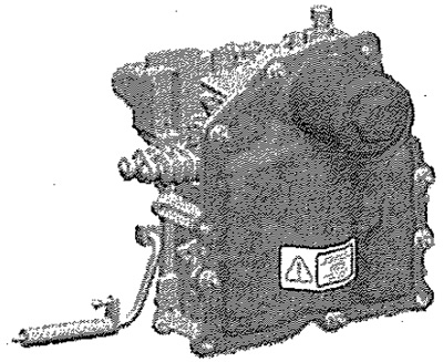
Fitting location: Mechatronic unit for double-clutch gearbox -L43- is screwed to the front of the gearbox housing. The control unit is integrated in the mechatronics unit for the double clutch gearbox -J743-. Checking is carried out by means of self-diagnosis. The mechatronics unit for the double clutch gearbox -J743- contains a sensor and actuators. Detailed information on this topic can be found in the description of a similar 7-speed automatic gearbox OAM, Remove mechatronic unit for double clutch gearbox -J743-. Installing mechatronics for double clutch gearbox -J743-.
Gearbox primary torque sender -G182-
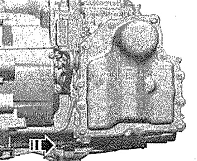
Fitting location: The gearbox input speed sender -G182- is attached to the gearbox housing at the front. To remove, unlock sensor and pull out in -direction of arrow-. Gearbox input speed sender -G182- can only be replaced in conjunction with mechatronics for double clutch gearbox -J743-, selector lever -E313- with tiptronic switch -F189-, selector lever sensor control unit -J587-, selector lever lock switch in position P -F319- and selector lever lock magnet -N110-. Installation location: Built into the shift mechanism and not replaced separately. Removal and installation is possible only with the switching mechanism.
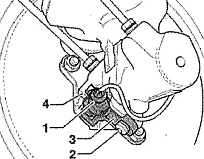
Brake light switch -F- and brake pedal switch -F47-
Fitting location: Brake light switch -F- and brake pedal switch -F47- -pos. 3- are located on the brake master cylinder -pos. 4-.
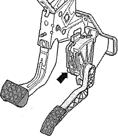
Accelerator pedal limit switch -F8-
The value from the accelerator position sender -C79-/accelerator position sender 2 -G185- is stored in the engine control unit as the kick-down signal (integrated into the accelerator pedal module). Fitting location: Accelerator position sender -C79- / Accelerator position sender 2 -G185- -See arrow - located in the pedal mechanism.