



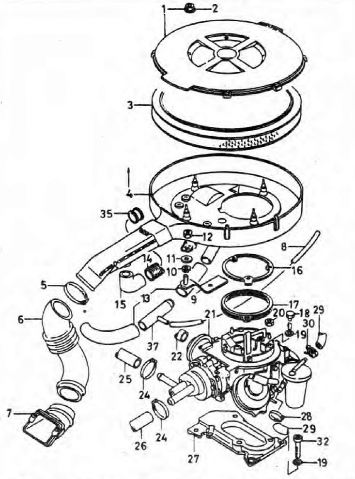
Fig. 4.5. Carburetor, air filter and related components
1. Air filter cover; 2. Nut; 3. Filter element; 4. Air filter body; 5. Bracket; 6. Inlet hose; 7. Adapter; 8. Ventilation hose; 9. Bracket; 10. Rubber bushing; 11. Washer; 12. Nut; 13. Ventilation hose; 14. Hot air hose; 15. Elbow branch pipe; 16. Mounting plate; 17. Gasket; 18. Screw; 19. Washer; 20. Nut; 21. Carburetor; 22. Hose; 24. Bracket; 25. Cooling system outlet pipe; 26. Cooling system inlet hose; 27. Mounting flange and gaskets; 28. Bracket; 29. Fuel hose; 30. Bracket; 32. Screw; 35. Tip; 37. T-connection.
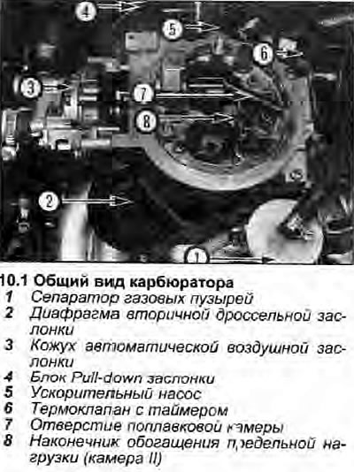
1. Carburetor Pierburg 2E3 (Jikov 28-30 LEKR) - dual-chamber with falling flow and vacuum secondary throttle valve (see illustration).
2. The carburetor forms a fuel-air mixture that corresponds to the operating conditions. This is achieved in the following way.
3. Fuel enters the carburetor through the filter and collects in the float chamber. The fuel level in the chamber is controlled by a float and a needle installed in the fuel inlet. When the fuel level in the chamber drops, the float drops and the needle opens the valve. When the fuel reaches the correct level, the regulator closes and the fuel supply stops. An air passage between the float chamber and the air filter prevents the pressure in the chamber from increasing and also reduces the effect of a clogged air filter on the fuel-air mixture.
4. A semi-automatic cold start system (choke) is used. When the engine is cold, the choke is actuated by a single (or double in frosty weather) by pressing the gas pedal. This activates the fast idle cam; the bimetallic spring closes the automatic choke and the fast idle cam moves to the fast idle position. When the accelerator pedal is released, the throttle valve moves to the cold start position and the fast idle adjustment screw rests against the highest notch on the fast idle cam.
5. When the ignition is turned on, the idle mixture shut-off valve opens, fuel is supplied to the carburetor, and the bimetallic spring in the choke cover is activated. As the engine cranks, the vacuum on the choke side increases and fuel is sucked in from the primary choke system. Over-enrichment of the mixture is prevented by the fact that the choke is installed slightly offset so that it is slightly open and a small amount of air always passes by.
6. When the engine starts, the vacuum in the diffuser drives the pull-down diaphragm, which opens the air damper, and additional air enters the system, preventing excessive enrichment of the mixture. The movement of the diaphragm rod is limited by a stop screw. Air passes into the "pull-down" block through a thermal valve with a timer, reducing the efficiency of the vacuum pull-down diaphragm in a cold state. When the thermal valve closes, the efficiency of the pull-down diaphragm increases, and the air damper opens further.
7. When the engine is warming up, any movement of the gas pedal acts on the lever, turning the fast idle cam. Resetting the fast idle speed adjuster screw to the part of the cam for the warm-up mode, accordingly reduces the degree of opening of the throttle valve.
8. As the engine temperature rises to normal operating temperature, the bimetallic spring and lever gradually open the choke, leaning the mixture. The fast idle screw moves to the extreme step of the warm-up stage on the fast idle cam. At normal operating temperature, the screw does not touch the cam, and the idle speed is determined only by the position of the throttle valve and the amount of mixture passing through the idle bypass circuit.
9. To prevent over-enrichment of the mixture during acceleration during the warm-up stage, the primary throttle valve and the choke valve are mechanically linked, and the choke valve always moves to the middle of the setting range.
10. To prevent flooding with fuel in the event of the throttle valve being fully opened when the engine is not yet warmed up, a special mechanism is activated by which the cam on the gas lever turns the throttle lever counterclockwise, partially opening the throttle.
11. The accelerator pump operates only when the throttle valve is less than half open. The pump is mechanically actuated by a lever and cam attached to the primary throttle rod. Less fuel enters the primary diffuser, and its excess returns to the float chamber through a calibrated channel.
12. The calibrated main jet regulates the amount of fuel supplied from the float chamber to the main air flow. A combined emulsion tube is installed at the base of the float chamber; corrective air jet, the fuel and air mixture passes through the auxiliary diffuser into the main air flow.
13. At idle and light operating conditions, the fuel outlet channel and the enrichment channel are blocked by vacuum pressure acting on the diaphragm. When the throttle valve is opened, the vacuum in the manifold decreases, the diaphragm returns under the force of the spring, the fuel channel valve opens and an additional amount of fuel begins to be supplied.
14. At low speeds, only the primary diffuser operates. When the air flow velocity through the primary diffuser reaches a certain level, the vacuum acting on the secondary diaphragm actuates the secondary throttle valve. A special jet prevents the occurrence of frequency oscillations caused by the beginning of the opening of the secondary throttle valve. As soon as the secondary throttle valve opens, the action of the secondary circuit becomes almost the same as that of the primary.
15. At full load and maximum engine speed, the air flow velocity creates a vacuum sufficient to draw fuel from the float chamber into the riser tube and then through the calibrated bushing into the upper part of the secondary air intake. From here, the fuel is fed into the air flow through the full load mixture enrichment tube.
16. The intake manifold is heated by coolant to improve the gas properties of the fuel-air mixture. For the same purpose, there is an electric heating device for the throttle body.
17. The vapor trap is mounted on a bracket on the side of the carburetor. Its function is to provide a continuous flow of fuel to the float chamber at high temperatures where vapors can cause erratic operation and difficult starting of the engine.
[View the original on the website: SkodaBook.ru]
18. The catch can is part of a calibrated return fuel system. Fuel that is not needed by the carburetor is returned to the tank. Thus, fuel is supplied to the carburetor only when it is relatively cold.