
Diesel engine lubrication system
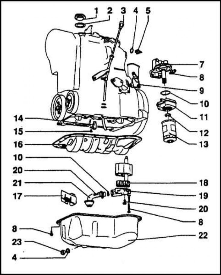
1 - Oil filler cap; 2 - Sealing gasket; 3 - Measuring probe; 4 - Sealing gasket; 5 - Sensor-switch of the oil pressure warning lamp; 7 - Oil filter bracket; 8 - Bracket mounting bolt; 9 - Seal; 10 - O-ring; 11 - Heat exchanger; 12 - Heat exchanger fastening nut; 13 - Oil filter; 14 - Oil jet connecting rod; 15 - Jet fastening bolt; 16 - Oil deflector; 17 - Oil deflector; 18 - Oil pump gears; 19 - Cover; 20 - Mounting bolt; 21 - Oil intake; 22 - Oil pan; 23 - Drain plug
Oil pump components
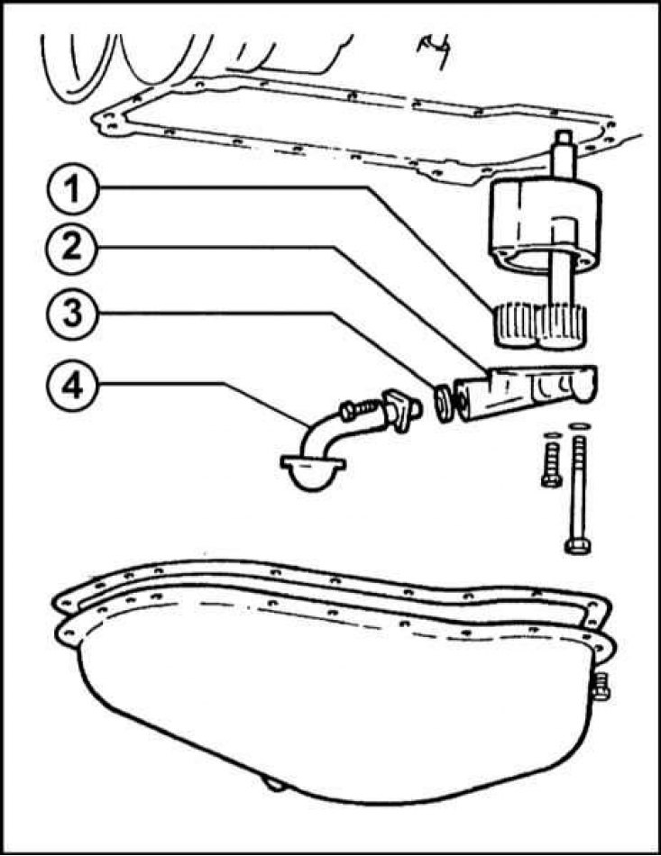
1 - Pump gears; 2 - Pump cover; 3 - O-ring; 4 - Oil intake tube
Lubrication system - general information
The engine in question uses a combined lubrication system with a full-flow oil filter. The total volume of oil to be filled is 4.5 liters.
The required operating oil pressure is generated by a gear oil pump. The width of the gears is 36 mm. The oil intake is connected to the pump through a sealing gasket. The working value of the oil pressure in the system is 0.57÷0.67 MPa. If the permissible value is exceeded, the pressure reducing valve of the pump opens.
The warning light switch is attached to the oil filter bracket.
The oil is cooled in a heat exchanger connected to the engine cooling system.
The oil pump and oil pickup assembly are located in the engine sump. The pump is driven by an intermediate shaft rotating at a frequency equal to half the crankshaft speed.
Removing
1. Remove the engine oil pan (see Section Pallet - removal, inspection and installation).
2. Turn out bolts of fastening of the pump to the basis of the block of cylinders.
3. Lower the pump/sump assembly, separating it from the block. If equipped, remove the oil deflector plate.
Examination
1. Loosen the screws securing the interface flange and remove the oil intake tube. Remove the sealing ring. Loosen the fixing screws and remove the pump cover.
2. Thoroughly clean the pump and check the condition of its gear teeth.
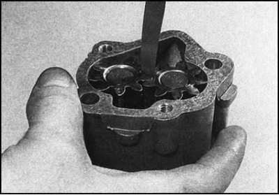
3. To estimate the amount of engagement play, rotate the gears in different directions. Take a measurement and compare it with the requirements Specifications.
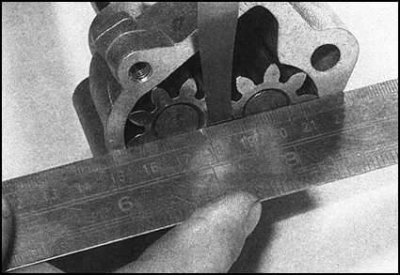
4. Using a steel ruler and a blade-type feeler gauge, determine the axial play of the gears. Compare the result with the requirements Specifications.
5. If the measurement results are out of range, the pump must be replaced.
Installation
1. Install the pump cover, screw in and tighten the mounting screws to the required force.
2. Install the oil pickup assembly on the pump (don't forget to replace the o-ring). Tighten the fixing screws to the required torque.
3. Establish the pump on the block of cylinders, screw and tighten fixing bolts with the demanded effort.
4. Reinstall the oil pan.