
Removing
1. Park your vehicle in a large, level, hard surface area.
2. Disconnect the negative cable from the battery.
3. Empty the cooling system (see chapter Current service).
4. Remove the accessory drive belt (see Section Removing, installing and adjusting the tension of the auxiliary drive belt).
5. Squeezing the locking tabs, release the spring clip and remove the air intake sleeve from the intake manifold cover.
6. Perform the following procedures (see chapter Cooling, heating systems):
- a) Release the clamps and disconnect the radiator hoses from the nozzles on the cylinder head;
- b) Release the clamps and disconnect the expansion tank hose, as well as the heater inlet and outlet hoses from the nozzles on the cylinder head.
7. In accordance with the instructions given in Chapter Supply system, perform the following procedures:
- a) Disconnect from the injectors and the injection pump head and remove the fuel supply pipes;
- b) Disconnect the injector return hose from the injection pump return fitting;
- c) Having previously clearly marked the wiring, disconnect all electrical connectors of the power system.
8. Acting in the manner described in Sections Bringing the piston of the first cylinder to the top dead center position (TDC) end of compression stroke, Removal and installation of the timing belt and its covers, Removal and installation of a cover of a head of cylinders, do the following:
- a) Remove the cylinder head cover;
- b) Remove the outer covers of the timing belt and throw off the belt from the camshaft gear;
- c) Remove the timing belt tensioner, as well as the camshaft and injection pump gears.
9. After removing the timing belt, the engine can be raised back to its original position, and the right implement support is connected.
10. In order to avoid accidental contact of the pistons with the valves during the removal of the head, the compilers of this Guide recommend turning the crankshaft back to a position a few degrees before TDC.
11. Turn out fixing screws and remove an internal cover of a gas-distributing belt.
12. In accordance with the instructions of the Chapter Supply system Chapters Engine electrical equipment perform the following procedures:
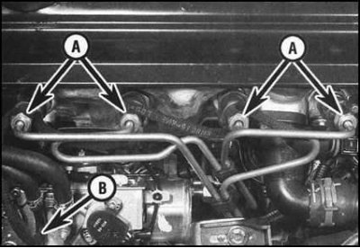
- a) Under the car turn out fixing bolts and separate a reception pipe of system of release of the fulfilled gases from a flange of a final collector;
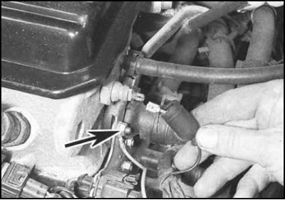
- b) Remove the EGR valve and its connecting fittings from the inlet pipeline and exhaust manifold;
- c) Unbolt the feed wire from the fourth cylinder glow plug.
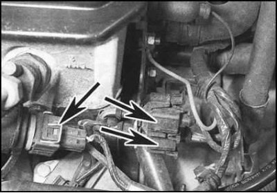
13. Disconnect the CTS wiring connector and the two connectors seated in the adjacent bracket.
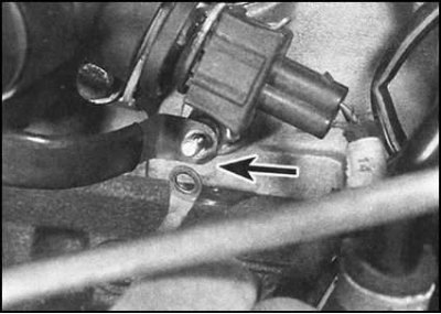
14. Disconnect the electrical wiring from the engine oil pressure sensor switch and the ground bus located below.

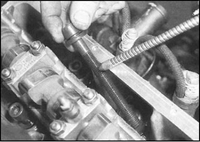
15. Acting in the order indicated in the illustration, in several steps (half a turn per approach) loosen the head bolts enough to be able to turn them out by hand. During assembly, the bolts must be replaced without fail.
16. Make sure that no communication lines remain connected to the cylinder head. Remove the head from the cylinder block (if necessary, use the help of an assistant, especially if the head is removed assembled with pipeline and manifold).
17. If the head "got used to" and cannot be separated from the block, in no case try to knock it down with hammer blows - do not forget about the guide pins! Instead, carefully rock the assembly by the piping/manifold - don't try to lever it between the mating surfaces!
18. Remove the gasket from the block mating surface. Don't throw it away by saving it as a template. Check the tightness of the guide pins, if necessary, remove them from their sockets.
Separation from intake manifold head and exhaust manifold
1. With the head on a workbench, remove the five intake manifold cover bolts. Remove the cover and its sealing gasket.
2. Turn out fixing bolts and remove from a head four inlet pipes in gathering with the pipeline. Remove the seal.
3. Loosen and remove the fixing nuts in several steps (during assembly, defective nuts must be replaced) and remove the exhaust manifold with gasket from the cylinder head.
4. Thoroughly clean the mating surfaces, install a new gasket, then install the exhaust manifold. Fit new fixing nuts and tighten them to the required torque.
5. Place a new gasket on the head, then install the intake manifold assembly on it. Alternately install each of the inlet pipes, then screw in the fixing bolts and tighten them with the required force.
Assembly preparation
1. Using a soft scraper, carefully clean the mating surfaces of the head and block. Remove all traces of old gasket material and carbon deposits from surfaces. Clean also the bottoms of the pistons. Try to keep debris out of water galleries and oil drains (carbon particles can tightly block the oil supply to the internal components of the engine) - seal all accessible holes with tape. The gaps between the walls of pistons and cylinders for the same purpose should be filled with grease, which can then be easily removed with a thin brush.
2. Check the mating surfaces of the block and cylinder head for scratches, scuff marks and other mechanical damage. Minor imperfections can be removed with a fine-toothed file or fine-grained sandpaper. In case of more serious damage, you will have to resort to machining. Assess the flatness of mating surfaces using a special template (ribs of steel ruler) and a blade type probe.
3. Drive the bolt holes in the cylinder block with a suitable tap, clearing the threads and repairing the damaged turns.
Note. In the absence of a suitable tap at hand, the holes can be cleaned using a homemade device made from a long hairpin with sawn threads along the thread.
4. To avoid damage to pistons and valves, the compilers of this Guide recommend that before installing the head, take the crankshaft 90°back from the TDC position (if necessary, refer to the materials of the Section Description of the main components and mechanisms).
Assembly
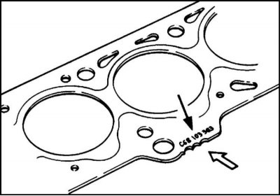
1. Make sure that the replacement gasket matches the size removed from the engine. Identification marking can be in the form of punched holes, scratches, or a letter number located along the edge of the gasket. If the pistons have not been replaced, a gasket of the same size as the one removed during dismantling must be installed on the engine.
2. Otherwise, a new gasket is selected according to the results of measurements of the height of the protrusion of the new pistons.
3. Thoroughly wipe the mating surfaces of the cylinder head and cylinder block with a clean, dry rag, then lay a new gasket on the block, carefully sliding it over the guide pins. If drive pins are not provided, a pair of thread cleaners manufactured in accordance with the instructions in paragraph 4 of subsection Preparing for Assembly of Thread Cleaners can be screwed into the bolt holes of the block instead. The gasket must be installed with the marking facing up.
4. With the help of an assistant, carefully slide the head assembly with tubing and manifold onto the guide studs. Before the final lowering of the head on the block, once again make sure that the gasket is correctly positioned.
5. Lightly coat the threads and bottom surfaces of the mounting bolt heads with machine oil.
6. Carefully thread each of the bolts into their hole and hand-tighten.
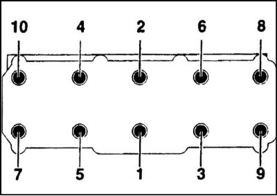
7. Tighten the bolts in sequence to the first stage torque in sequence, then repeat the procedure and tighten the bolts to the second stage torque.
8. Having tightened the bolts with the force of the second stage, use a special goniometer or a template made of thick cardboard and tighten the bolts to the angle of the third stage of tightening. Finally, tighten the bolts to the fourth stage corner.
9. Reinstall the inner timing belt cover, firmly tighten the bolts of its fastening.
10. Bring the engine to TDC (see Section Bringing the piston of the first cylinder to the top dead center position (TDC) end of compression stroke).
11. Support the engine, disconnect the right support and lower the power unit slightly (see Section Removal and installation of the timing belt and its covers). Now reinstall the timing belt gears (see Section Removal and installation of the tensioner and gears of the timing belt). Install the belt and adjust its tension, then reinstall the outer covers and the crankshaft pulley (see Section Removal and installation of the timing belt and its covers).
12. The engine can now be lifted up again and the power unit supports reinstalled (see Section Removal and installation of the timing belt and its covers).
13. Install the accessory drive belt and adjust its tension (see Section Removal and installation of the timing belt and its covers).
14. Further installation is carried out in the reverse order of dismantling:
- a) A description of the installation procedures for the EGR valve and the glow plug power wire is given in Chapter Supply system;
- b) Following the instructions given in the chapter Supply system, connect the fuel supply hoses to the injectors and injection pump head. Restore the original power system wiring connection. Connect the return hose to the corresponding fitting of the injection pump;
- c) Do not forget to connect the multi-pin connector of the engine wiring harness;
- d) Reinstall the cylinder head cover (see Section Removal and installation of a cover of a head of cylinders);
- e) Refer to chapter materials Cooling, heating systems restore the original connection of the radiator and expansion tank hoses. Connect electrical wiring to CTS;
- f) Connect the negative wire to the battery.
15. Finally, fill the engine with the required amount of engine oil of the required grade.