
Heater and its installation in the cab
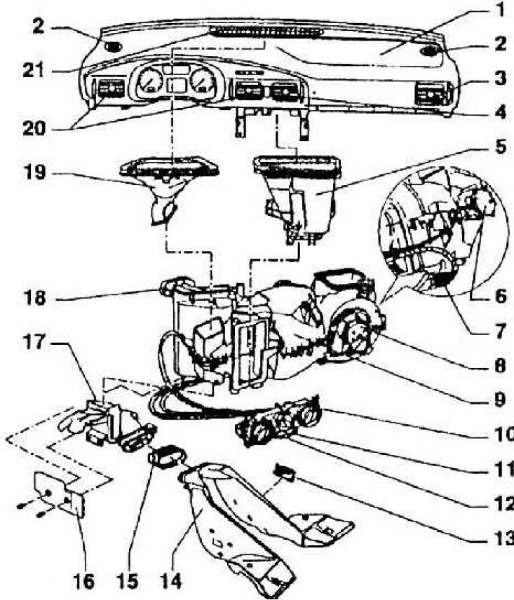
1 - dashboard; 2 - ventilation hatch for demisting side windows; 3 - ventilation hatch right; 4 – ventilation hatch middle right; 5 – an intermediate detail of the distributor of air; 6 – circulation damper servomotor; 7 – additional fan resistance; 8 - fan; 9 - air conditioner; 10 - heater control; 11 - fresh and recirculated air switch; 12 - air conditioner switch; 13 - ventilation hatch; 14 - air distributor on the rear floor; 15 - an intermediate part of the air distributor on the rear floor; 16 – a cover of the distributor of air of a forward floor left; 17 - front floor air distributor; 18 - heat exchanger; 19 - an intermediate piece to the ventilation hatch; 20 - ventilation hatch left and middle left; 21 - ventilation hatch for defrosting the windshield
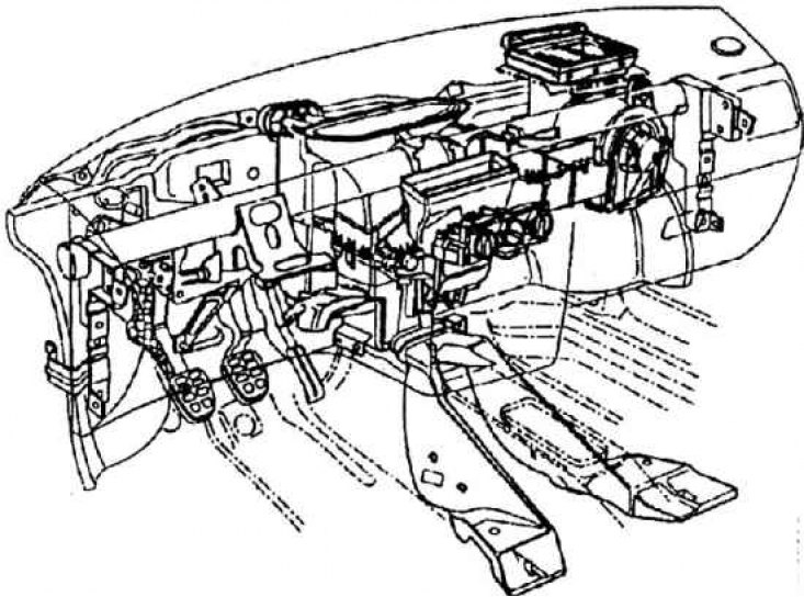
Installing the heater and fan assembly on the transverse wall of the passenger compartment
Dismantling and installation of the dust filter
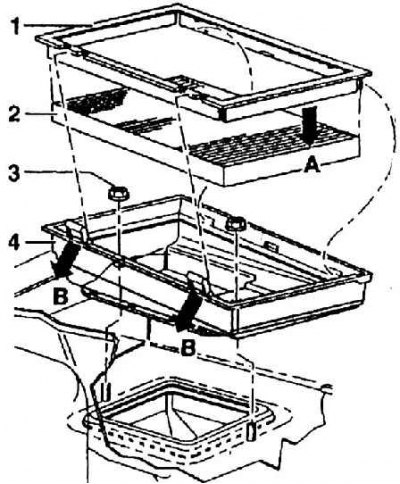
1 - frame; 2 - filter insert; 3 - plastic nut; 4 - filter box with seal
Dismantling: dismantle the right casing of the upper part of the transverse wall; remove the clamps of the filter box in the direction of arrows B and remove the filter together with the frame.
Mounting: framed (1) must be pushed up to the first layers of the filter insert (A).
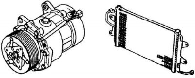
Air conditioner compressor and condenser
Air conditioner refrigerant circuit diagram
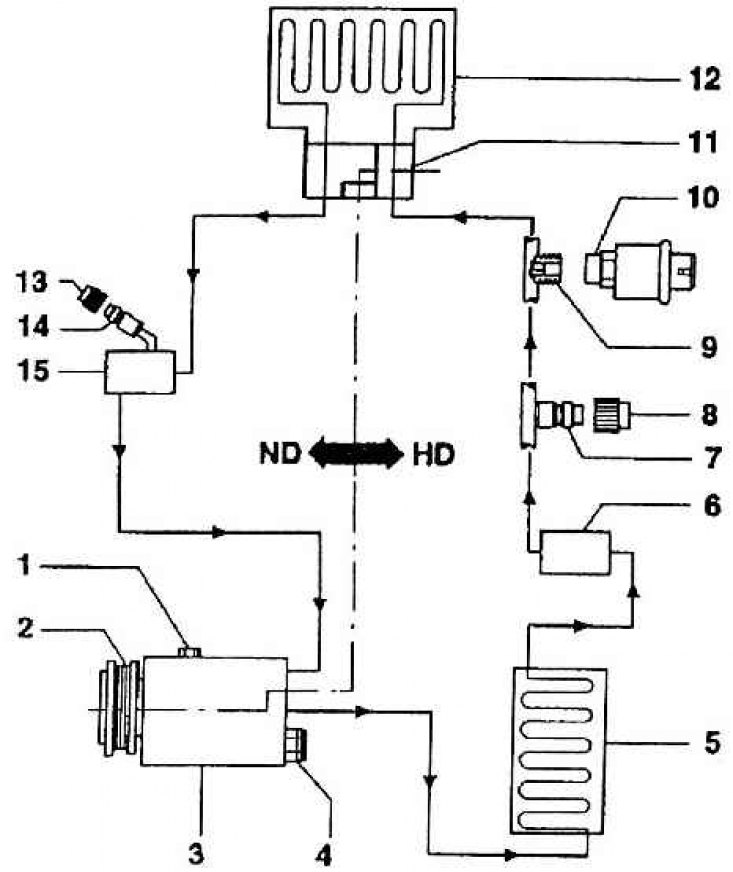
HD – high pressure branch; ND - low pressure branch; 1 - oil drain screw; 2 - electromagnetic clutch; 3 - compressor; 4 - overpressure safety valve; 5 - capacitor; 6 - a tank for liquid with a desiccant; 7 - valve for suction, filling and measurement; 8 - plug; 9 – inlet with valve; 10 - button to turn on the air conditioner; 11 - expansion valve; 12 - evaporator; 13 - plug; 14 - valve for suction and measurement; 15 - damper
One of the mounting units of the transverse wall of the passenger compartment is a heater (see fig. The heater and its installation in the cab, fig. Installing the heater and fan assembly on the transverse wall of the passenger compartment) or an air-conditioned heater. It follows that a large number of parts are suitable for both the heater and the air conditioner. Moreover, this is one of the nodes unified with other cars of the VW concern. Specifically, both the heater and the air conditioner used in Skoda Octavia cars differ from the concern's design only in terms of the control panel and air distribution. The coolant flow through the heater heat exchanger is constant, the heater does not have a valve in the coolant flow system. Control of the amount of air passing through the heat exchanger of the heater. and therefore, the power of the heat exchanger is carried out by the left rotary head of the regulator on the control panel. In cooling mode (regulator on the blue field) the airflow is greater than when the regulator is in the red field. This is because there is more resistance, or back pressure, as air passes through the heat exchanger of the heater. A detailed description of the adjustment of the heater, fan and air conditioner is given in the SERVICE INSTRUCTIONS. Air for heater (or fan) is taken from the chute in front of the windshield, covered by the hood. Air enters the heater through a dust filter (see fig. Dismantling and installation of the dust filter). The filter is made of artificial fibers. The active surface of the filter is increased by folding the cloth. By removing the plastic frame, you can change the filter insert. The holder with the filter is placed in the gutter, and the outlet from it passes along the bottom of the gutter and is fixed on the heater neck. In this neck there is a recirculation damper controlled by an electric motor (servomotor) switched on, as already mentioned, with a button on the control panel of the heater.
Then the air enters the turbine wheel of the fan, on the horizontal axis of which there is an electric motor. By flowing around the mixing damper, the air flow passes either through the heater heat exchanger or past it (fully or partially). The heat exchanger of the heater is standard, which means that these are aluminum tubes inserted with rubber tabs into the side chambers. The tubes are equipped with leaf blades. Further, in the heater housing, the air is distributed by means of dampers to the air distributor. All heater dampers are controlled by rotary regulators using rods in flexible shells.
In the case of installing a heater with air conditioning, the same elements are used for the heater as for one heater, only a box with an evaporator is also inserted between the fan and the chamber with a mixing damper. In the air conditioner, of course, there are more parts that are not, however, part of the heater.
It's about the capacitor (a narrow radiator located in front of the engine coolant radiator; see fig. Air conditioner compressor and condenser), valve for filling and pumping out the coolant and for measuring (low pressure), compressor, liquid tank with dryer, valve for pumping, filling and measuring (high pressure and expansion valve). The cooling medium is an environmentally friendly refrigerant R 134a, which is used to fill the air conditioners of all cars of the VW concern.
The principle of operation of the air conditioner is as follows (see fig. Air conditioner refrigerant circuit diagram): the refrigerant from the compressor under pressure in the gaseous state enters the condenser (radiator), where it liquefies. From there, it enters the dryer, in which, as in a filter, moisture and, if any, oil are separated. Then it enters the expansion valve through the hose - all the time in a liquid state. In the expansion valve, it expands and changes its phase state to gaseous while simultaneously entering the evaporator (cooling part of the air conditioner inserted into the heater kit). It removes heat from the passing air and returns it to the compressor. The compressor is placed on a common console with a generator. Mounting is different for different types of engines. The air conditioning compressor itself is a seven-piston with a smooth change in piston stroke. The stroke changes according to the inclination of the bevel of the plate, during the rotation of which the pistons move in the cylinders. The total volume of the compressor cylinders in the range of 161.3–8.1 cm33. Each 29.3mm piston has a stroke of 1.7 to 34.2mm. Operating speed - 8000 min. The maximum working pressure is 3.25 MPa. Filling oil into the compressor - 135±15 cm3. The oil is special and does not change or top up. However, a complete change can be carried out in the event of an A/C refrigerant leak. (Only in the Skoda service, which is specialized in this operation!)
The air conditioner is turned on when the compressor is turned on. An electromagnetic clutch is inserted into the compressor pulley, which constantly rotates the pulley (during engine operation), connected to the compressor drive shaft. The dryer is placed on the right side of the condenser. From an accidental rise in the temperature of the engine coolant, depending on the operation of the air conditioner, it is protected by a thermal switch located in the plastic box of the thermostat together with the engine coolant temperature sensor. The thermal switch turns off the air conditioner if the engine coolant temperature reaches 114°C (to prevent engine overheating).
In conclusion, it must be emphasized that the above description is purely informative. Unqualified intervention in the air conditioner and its parts is unacceptable. Any defect should be eliminated only in the Skoda service.