Note: Please refer to the note given at the beginning of the Chapter 9 and the warning given at the beginning Chapter 13 (regarding asbestos dust).
Inspection
Note: To ensure equal and effective braking, the discs of both front brakes should be changed at the same time, even if only one of them is damaged.
1. Jack up the front of the vehicle and place it securely on axle stands, then remove the wheel.
2. Slowly rotate the brake disc so that you can fully inspect its surface on both sides; remove the brake pads (see Chapter 13). if better access is required to the inner surface. The presence of light scratches in the area covered by the brake pads is perfectly acceptable, but if deep grooves are found, the disc must be replaced. The only alternative to this is to grind the disc until the surface is smooth again, but the thickness of the disc must not be less than specified in Specifications minimum value.
3. The presence of a protrusion formed by rust or adhering dust on the periphery of the disk is quite acceptable. This thickening can be scraped off. If, however, a difference in thickness has formed due to wear in the area covered by the pads, measure the thickness of the disc with a micrometer. Take measurements in several places, in and out of the pad contact area. If at least one of the dimensions is equal to the specified in Specifications minimum thickness or less, replace the disc.
4. If the disc is suspected to be warped, check it for runout with a micrometer (5 mm from the outer edge of the disc). Alternatively, rotate the disc slowly and use a feeler gauge to take several measurements of the gap between the disc and a fixed point, such as the caliper mounting bracket. If the measurements obtained are equal to or greater than those specified in Specifications at most, the disk is warped and must be replaced. However, first check the condition of the wheel bearings (Sections 1 and/or 10). Try also to remove the disk and turn it 180°relative to the hub; if disc runout is still excessive, the disc should be replaced.
5. Check the disc for cracks. especially around bolt holes, and any other damage and wear. Replace the disk if any are found.
Removing
6. Jack up the front of the vehicle, place it securely on axle stands, then remove the wheel.
7. See Chapter 14 and unscrew the two bolts securing the caliper bracket to the steering knuckle, then remove the caliper assembly, move it to the side and tie it to the body, being careful not to stretch or bend the brake hose. Place a makeshift clean spacer between the pads (the same thickness as the brake disc), to prevent them from moving.
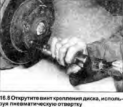
8. Using chalk or paint, mark the alignment marks on the disc and hub, then unscrew the mounting screw and remove the disc. The screw can be very tight, in which case you will need a pneumatic screwdriver (see photo).
Installation
9. Install in the reverse order of removal paying attention to the following:
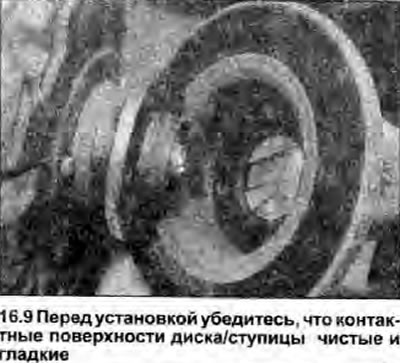
- a) Make sure the contact surfaces of the disc and hub are clean and even (see photo).
- b) Align the marks made before removing the marks.
- c) Tighten the disc screw, caliper bracket mounting bolts and wheel bolts with a tightening torque specified specifications.
- d) If a new drive is being installed, use a suitable solvent to remove the protective coating from the drive.