



Contents: Assembly diagram for engines with…⬇ Assembly diagram for the engine with…⬇ Rear of the exhaust manifold ⬇
Assembly diagram for engines with letter designations BNM, BNV
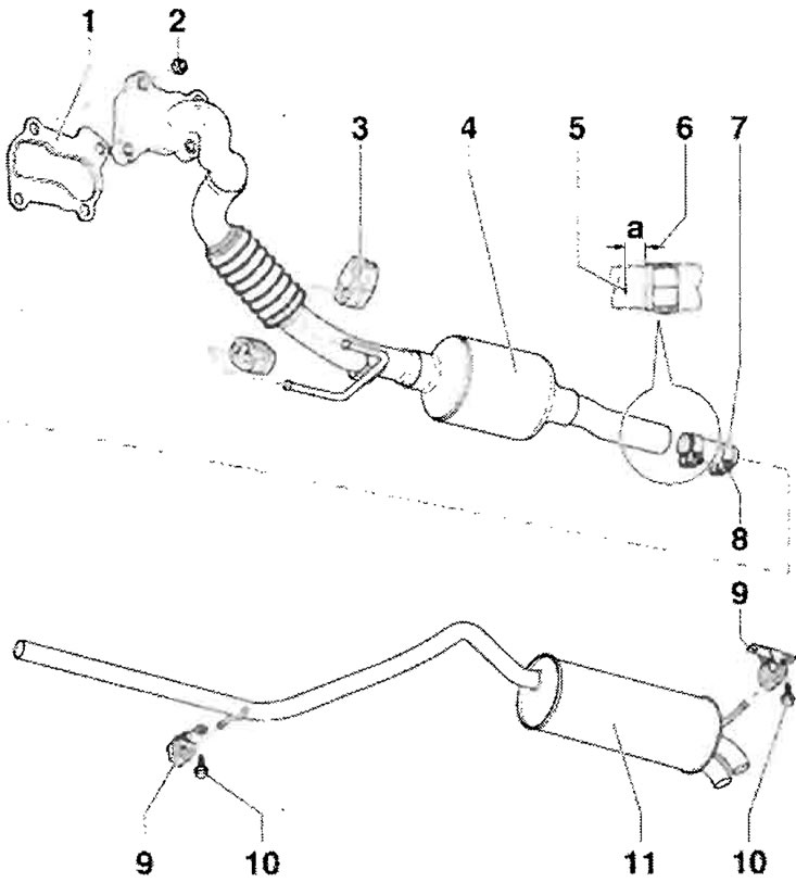
1 - Seal, replace; 2 - 25 Nm, replace, lubricate studs with paste for connections subject to thermal stress "G 052 112 A3"; 3 - Spring suspension, replace if damaged; 4 - Front section of exhaust pipe, with catalytic converter, with flexible connection element, the flexible connection element must not be bent more than 10° - risk of damage, align the exhaust system so that it is free of internal stress; 5 - Marking; 6 - Size "a" = approx. 5 mm; 7 - Double clamp, before tightening, adjust the exhaust system so that there is no internal stress on it, tighten the screw connections evenly; 8 - 23 Nm; 9 - Spring suspension, replace if damaged; 10 - 25 Nm; 11 - Middle and rear parts of the exhaust pipe, from the factory the middle part of the exhaust pipe forms one piece together with the rear part of the exhaust pipe, in case of repair replace separately, assemble the exhaust system without internal stress
Assembly diagram for the engine with the letter designation BMS
Front exhaust manifold with particulate filter
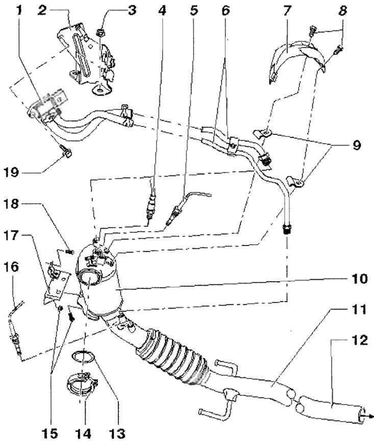
1 - Exhaust gas pressure sensor 1 "G450"; 2 - Holder; 3 - Nut; 4 - Lambda probe "G39" 50 Nm, lubricate only the threads with paste for connections subject to thermal stress - G 052 112 A3; do not allow the paste to get into the slots of the probe body; 5 - Exhaust gas temperature sensor 2 for bank 1 "G448" - 45 Nm, lubricate only the threads with paste for threaded connections subject to thermal stress "G 052 112 A3"; 6 - Pressure pipeline - 45 Nm; 7 - Heat-protective casing; 8 - 9 Nm; 9 - Holder for pressure pipeline; 10 - Particulate filter; 11 - Front part of the exhaust manifold; 12 - Marking for double clamp; 13 - Seal, replace, observe the assembly position; 14 - Clamp, 7 Nm; 15 - 25 Nm; 16 - Temperature sensor behind the particulate filter "G527" - 45 Nm, lubricate only the threads with paste for threaded connections subject to thermal stress "G 052 112 A3"; 17 - Holder, screwed onto the cylinder block; 18 - 25 Nm; 19 - 8 Nm
Rear of the exhaust manifold
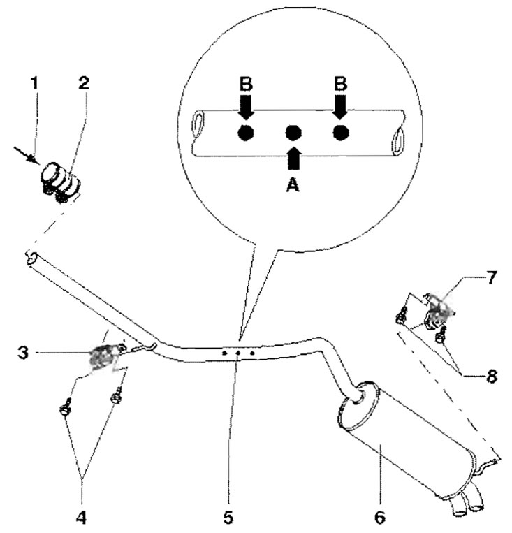
1 - From the particulate filter; 2 - Double clamp, 23 Nm; 3 - Spring suspension, replace if damaged; 4 - 25 Nm; 5 - Cutting location, from the factory the rear part of the exhaust pipe forms one piece together with the middle part of the exhaust pipe, in case of repair they are replaced separately, during installation the double clamp should be positioned on the marking "arrow B", align the exhaust system so that there is no internal stress on it; 6 - Rear of the exhaust pipe; 7 - Spring suspension, replace if damaged 8-25 Nm