



Contents: Assembly location diagram for…⬇ Details in the footwell ⬇ Relay panel ⬇ Removal and installation the…⬇ Disassembling and assembling the air…⬇ Assembly location diagram for the…⬇ Removal and installation the intake…⬇ Disassembling and assembling the air…⬇
Assembly location diagram for engines with letter designations BNM, BNV
Parts marked with letters A through H are not shown on the assembly location diagram.
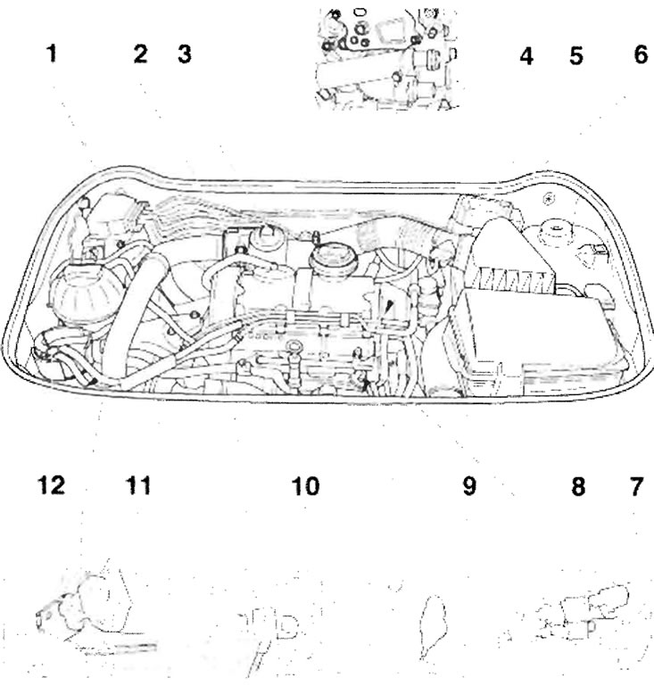
A - Direct fuel injection system relay. diesel engine "J322", on the relay panel; B - Glow plug relay "J52", on the relay panel; C - Low heat output relay "J359", on the relay panel; D - High-output relay "J360", on the relay panel; E - Fuel pump relay "J17" on the relay panel; F - Accelerator pedal position sensor "G79" and accelerator pedal position sensor 2 "G185", in the footwell on the accelerator pedal (both sensors are located in the same housing); G - Brake light switch "F" and brake pedal switch "F47", in the footwell on the brake pedal; H - Clutch pedal switch "F36", in the footwell on the clutch pedal; 1 - Valve block, the components of the valve block are: electromagnetic valve for exhaust gas recirculation "N18", the required resistance value: 14-20 Ohm, electromagnetic valve for limiting the boost pressure "N75", the required resistance value: 25-45 Ohm; 2 - Throttle valve motor in the intake manifold "V157"; 3 - Mechanical valve of the exhaust gas recirculation system, on the intake manifold with a flap in the intake manifold; 4 - Coolant temperature sensor "G62", required resistance value; 5 - Air flow meter "G70"; 6 - Engine control unit "J623"; 7 - Fuel temperature sensor "G81"; 8 - Plug connector, three-pin, gray, engine speed sensor "G28", three-pin, black, camshaft position sensor "G40"; 9 - Engine shaft speed sensor "G28", required resistance value between contacts 1 and 2: 450-550 Ohm; 10 - Camshaft position sensor "G40"; 11 - Intake air pressure sensor "G71" with intake air temperature sensor "G72"; 12 - Fuel filter, (the figure shows the fuel filter used in the 1.4 l/55 kW TDI engine with the letter designation AMF)
Details in the footwell
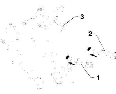
- 1 - Clutch pedal switch "F36"
- 2 - Brake light switch "F" and brake pedal switch "F47"
- 3 - Accelerator pedal position sensor "G79" and accelerator pedal position sensor 2 "G185"
Relay panel
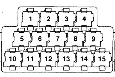
- 8 - High-output relay "J360"
- 9 - Glow plug relay "J52"
- 13 - Direct fuel injection system relay "J322"
- 14 - Fuel pump relay "J17"
Removal and installation the turbocharger intake manifold flap for engines with the letter designations BNM, BNV
After the engine is turned off, the throttle valve in the intake manifold closes for about 3 seconds and then opens again. This reduces the shock when turning off.
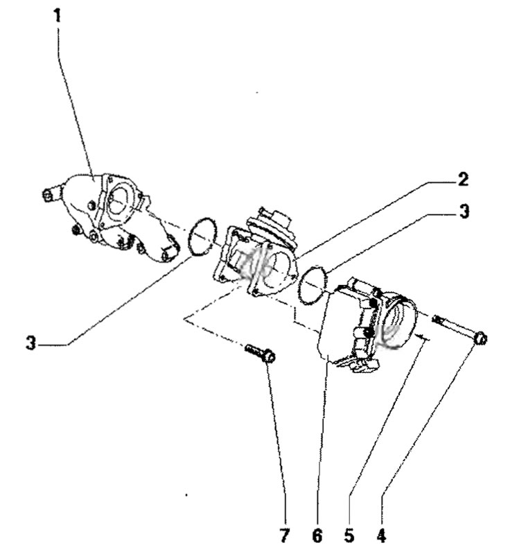
1 - Intake gas pipeline; 2 - Inlet manifold, with mechanical EGR valve; 3 - O-ring seal, replace; 4 - 10 Nm; 5 - from the intercooler; 6 - Throttle valve motor in the intake manifold "V157"; 7 - 10 Nm
Disassembling and assembling the air filter for engines with the letter designations BNM, BNV
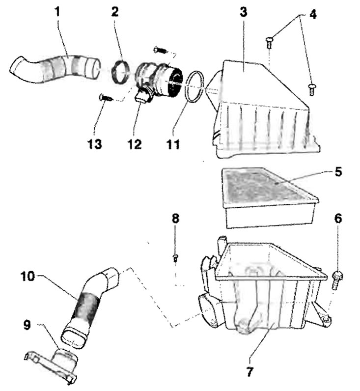
1 - Inlet hose, to the inlet manifold, observe the correct position for assembly; 2 - Spring clamp; 3 - Upper air filter housing; 4 - 2 Nm; 5 - Filter element of the filter '; 6 - 8 Nm; 7 - Lower air filter housing; 8 - 2 Nm; 9 - Inlet manifold; 10 - Air duct, to the front wall of the body; 11 - Sealing ring; 12 - Air flow meter "G70"; 13 - 6 Nm
Assembly location diagram for the engine with the letter designation BMS
Parts marked with letters A through H are not shown on the assembly location diagram.
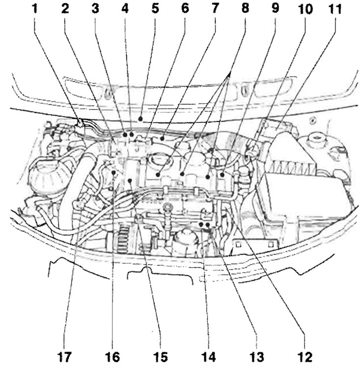
A - Relay for direct fuel injection system of diesel engine "J322", on the relay panel; B - Preheating control unit (incandescence) "J179", in the engine compartment near the battery; C - Low heat output relay "J359", on the relay panel; D - High-output relay "J360", on the relay panel; E - Fuel pump relay "J17", on the relay panel; F - Accelerator pedal position sensor "G79" with accelerator pedal position sensor 2 "G185", in the footwell on the accelerator pedal (both sensors are located in the same housing); G - Brake light switch "F" and brake pedal switch "F47", in the footwell on the brake pedal; H - Clutch pedal switch "F36", in the footwell on the clutch pedal; 1 - Solenoid valve for limiting boost pressure "N75"; 2 - Intake manifold flap motor "V157"; 3 - Lambda probe "G39" with heated lambda probe "Z19"; 4 - Temperature sensor before the particulate filter "G448"; 5 - Temperature sensor behind the particulate filter "G527"; 6 - EGR valve "N18" with EGR potentiometer "G212" and EGR regulator "V338"; 7 - Pressure sensor 1 before turbocharger "G235"; 8 - Unit-injector assemblies, unit-injector valve, cylinder "N240", unit-injector valve, cylinder 2 "N241", unit-injector valve, cylinder 3 "N242"; 9 - Coolant temperature sensor "G62"; 10 - Air flow meter "G70"; 11 - Engine control unit "J623"; 12 - Multi-pin plug connector, central for pump-injector units; 13 - Fuel temperature sensor "G81"; 14 - Engine shaft speed sensor "G28"; 15 - Hall sensor "G40", camshaft position; 16 - Exhaust gas pressure sensor 1 "G450"; 17 - Boost pressure sensor "G31" with intake air temperature sensor "G42"
Removal and installation the intake manifold flap for an engine with the letter designation BMS
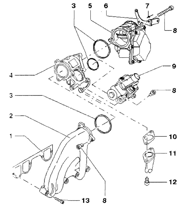
1 - Seal, replace, observe the assembly position; 2 - Intake gas pipeline; 3 - O-ring, replace; 4 - Fitting; 5 - Intake manifold flap motor "V157". After the engine is started, the intake manifold flap closes for approximately 3 seconds and then opens again. This reduces the shock when turning off; 6 - Holder; 7 - From the charge air cooler; 8 - 10 Nm; 9 - EGR valve "N18" with EGR circuit potentiometer "G212" and EGR regulator "V338", before installation, check the sealing surfaces on the intake manifold for contamination and, if necessary, clean them; 10 - Seal, replace; 11 - Radiator, exhaust gas recirculation system; 12 - 22 Nm; 13 - 22 Nm
Important: After replacement, the new part should be adjusted in the following manner: turn the ignition on and off; then wait 1 minute for the control units to run out of inertia, start the engine and let it run for at least 12 minutes at idle speed, the fault memory must not be cleared so that no fault is loaded into the memory. In case of a loaded fault, the contents of the fault memory should be reset and the entire procedure should be repeated.
Disassembling and assembling the air filter for an engine with the letter designation BMS
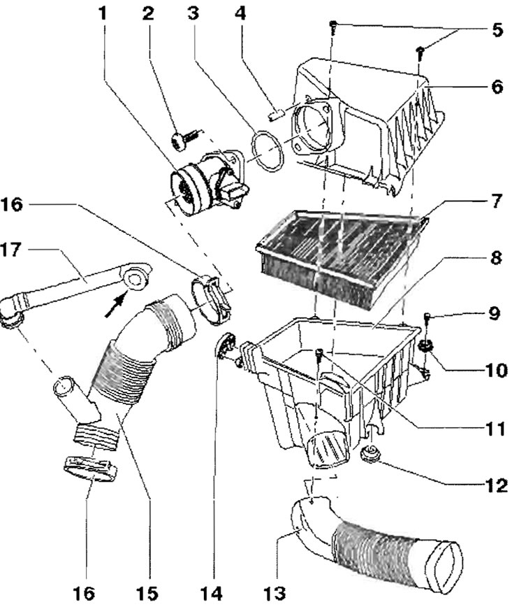
1 - Air flow meter "G70"; 2 - 2 Nm; 3 - O-ring seal, replace; 4 - Intake hose; 5 - 2 Nm; 6 - Upper air filter housing; 7 - Filter element; 8 - Lower air filter housing; 9 - 10 Nm; 10 - Rubber bushing; 11 - 2 Nm; 12 - Rubber bushing; 13 - Air duct, to the front wall of the body; 14 - Rubber bushing; 15 - Inlet hose to turbocharger, for northern countries - heated; 16 - Spring clamp; 17 - Connecting pipe, from the cylinder head cover, for crankcase ventilation