
Company vehicles Hyundai Company vehicles Kia Company vehicles Lada Company vehicles Mazda Company vehicles Mercedes-Benz Company vehicles Opel Company vehicles Mitsubishi
English Русский
Български
Беларускі
Український
Српски
Hrvatski
Română
Polski
Slovenský
Magyar
Articles   
Bookmark Contacts Sitemap
SkodaBook.ru


Fabia Rapid Octavia Superb Kodiaq Yeti Others
Fabia 2 (2007-2014) Fabia 1 (1999-2007)

Removal and installation of exhaust system components (Skoda Fabia 5J)

  • Main
  • Fabia
  • 5J (2007-2014)
  • Petrol engines 1.6 l
  • Power and control system
  • Removal and installation of exhaust system components
0
Contents: Assembly diagram of the front…⬇ Assembly diagram of the rear part of…⬇ Replacement of the middle pipe,…⬇
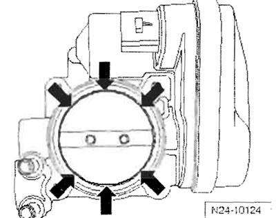
Important: When carrying out assembly work on the exhaust system, ensure that the exhaust system is mounted without pre-tensioning and that sufficient distance between the system and the body is maintained. If necessary, loosen the clamps and center the exhaust silencers and exhaust pipes so that there is a sufficiently large distance between these parts and the body and so that the load on the individual suspensions is uniform. The self-locking nuts need to be replaced.

Important: When carrying out assembly work on the…


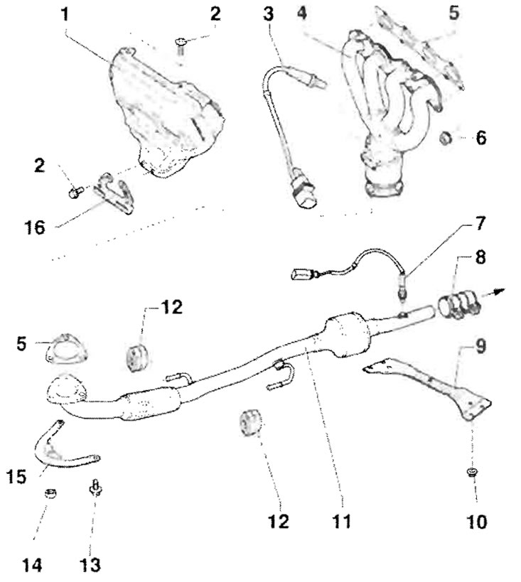
Assembly diagram of the front section of the exhaust manifold with exhaust catalytic converters


1 - Air heater/hot air screen; 2 - 10 Nm; 3 -…

1 - Air heater/hot air screen; 2 - 10 Nm; 3 - Lambda probe before catalytic converter - G39-, 50 Nm, lubricate only the threads with paste for connections subject to thermal stress - G 052 112 A3; do not allow paste for connections subject to thermal stress to get into the splines of the probe body. 4-pin plug connector in the holder near the engine starter; 4 - Exhaust manifold, with additional catalytic converter, to protect against impacts and shock loads; 5 - Seal, replace; 6 - 25 Nm, replace, before proceeding with installation, lubricate the exhaust manifold studs with paste for connections subject to thermal stress "G 052 112 A3"; 7 - Lambda probe behind the catalytic converter "G130", 50 Nm, lubricate only the threads with paste for connections subject to thermal stress "G 052 112 A3"; do not allow the paste for connections subject to thermal stress to get into the splines of the probe body. 4-pin curtain connector in the cover on the floor of the car under the right trim; 8 - Double clamp, 25 Nm, before tightening, assemble the exhaust system in one position so that it does not have internal stress, evenly tighten the screw connections; 9 - Tunnel Bridge(crossbar); 10 - 25 Nm; 11 - Protect the front section of the exhaust manifold with the main catalytic converter from impacts and shock loads; 12 - Spring suspension, replace if damaged; 13 - 20 Nm; 14 - 40 Nm, replace, before purchasing for installation, you should lubricate the studs of the additional catalytic converter with paste for connections subject to thermal stress "G 152 112 A3"; 15 - Holder; 16 - Wiring harness holder


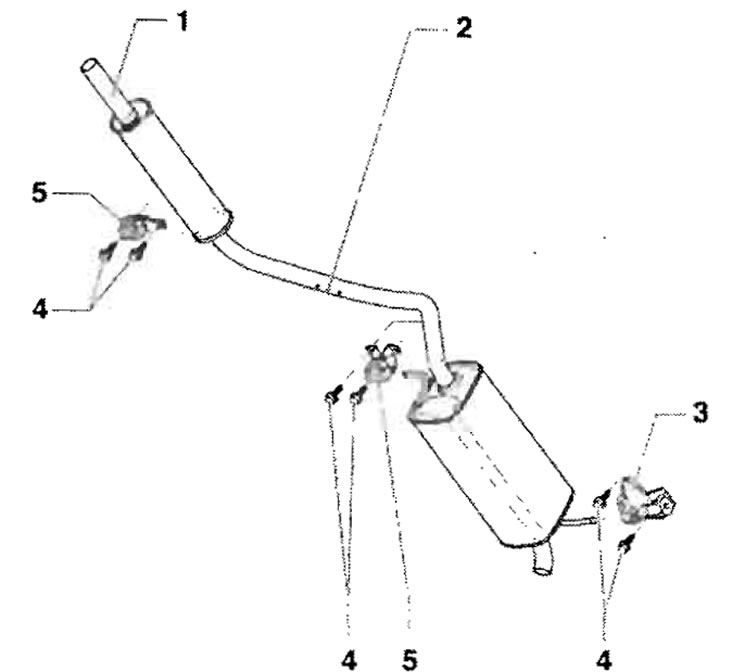
Assembly diagram of the rear part of the exhaust manifold


1 - The middle and rear parts of the exhaust…

1 - The middle and rear parts of the exhaust pipe, from the factory they form a single unit, in case of repair they must be replaced separately, the cutting point, align the exhaust system so that there is no internal stress on it; 2 - The cutting location, in case of repair, is indicated by pressed-out recesses on the perimeter; 3 - Spring suspension, rear, refer to the part number, replace if damaged; 4 - 25 Nm; 5 - Spring suspension, refer to the part number, replace if damaged


Replacement of the middle pipe, respectively, and the rear parts of the exhaust


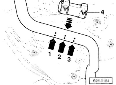
A cutting point is provided for replacing the front and rear parts of the exhaust pipe, respectively, in case of repair. The cutting location is indicated on the perimeter of the exhaust pipe by stamped recesses. Cut the exhaust pipe perpendicularly at the cutting point "arrow 2".
A cutting point is provided for replacing the…


When installing, position the double clamp "4" between the outer marks "arrow 1" and "arrow 3." Install the double clamp so that the screw ends do not protrude beyond the bottom edge. Align the exhaust system in a cold state so that it is free of internal stress.
This article is available at russian, bulgarian, belarusian, ukrainian, serbian, croatian, romanian, polish, slovak, hungarian
Article verified: Ekaterina Blinova
Share with friends:
◀ Previous
Skoda Fabia 2: Power and control system
Next ►

Fuel injection system repair
Ventilation system with activated carbon
Electronic fuel management system (without mechanical connection of the…
Removal air from the fuel system
Removal and installation the fuel tank
Ignition system
Removal and installation ignition coils with final power stages
Read similar articles on other Skoda models

➧ Precautions when working with Supplemental Restraint System (SRS)… Skoda Rapid 1 (2012-2022)
➧ Adjusting exhaust system components to relieve stress Skoda Octavia 3 (2013-2019)
➧ Checking the condition of the exhaust system Skoda Superb 2 (2008-2015)
➧ 1.4L Engine Management System Components Skoda Kodiaq 1 (2016-2024)
➧ Checking the condition of the exhaust system Skoda Yeti (2009-2017)
➧ Exhaust system — general description and replacement of components Skoda Favorit (1987-1994)
Link to this article in various formats
Reviews and comments of visitors
No comments yet


Add two numbers: 30 + 15


Fabia 2 (2007-2014) 
  • General information
  • User manual
  • Maintenance
  • Petrol engines 1.2 l
  • Engine repair
  • Cooling and lubrication system
  • Power and control system
  • Petrol engines 1.4 l
  • Engine repair
  • Cooling and lubrication system
  • Power and control system
  • Petrol engines 1.6 l
  • Engine repair
  • Cooling and lubrication system
  • Power and control system
  • Diesel engines 1.4 l
  • Engine repair
  • Cooling and lubrication system
  • Power and control system
  • Diesel engines 1.9 l
  • Engine repair
  • Cooling and lubrication system
  • Power and control system
  • Transmission
  • Manual gearbox 02R
  • Manual gearbox 02T
  • Automatic gearbox 09G
  • Cardan shaft
  • Chassis (running gear)
  • Front suspension
  • Rear suspension
  • Wheels and tires
  • Brake system
  • Steering system
  • Body and interior
  • Exterior (external elements)
  • Interior (internal elements)
  • Heating and air conditioning
  • Electrical equipment
  • Equipment and devices
  • Headlights and lighting
  • Power devices
  • Electrical circuits
Fabia 1 (1999-2007) 
  • User manual
  • Introduction to manual
  • Governing bodies
  • Salon equipment
  • Driving and maintenance
  • Power unit
  • Engine repair
  • Lubrication system
  • Supply system
  • Cooling system
  • Exhaust system
  • Transmission
  • Mechanical gearbox 002
  • Mechanical gearbox 02T
  • Chassis (running gear)
  • Front suspension
  • Rear suspension
  • Steering
  • Steering gear without power
  • Power steering
  • Brake system
  • Body and interior
  • Body and interior repair
  • Interior heating
  • Electrical equipment
  • Equipment and devices
  • Ignition system
  • Windshield wipers
  • Electrical circuits
SkodaBook.ru © 2018–2026 | Mobile version | Articles on Skoda | Sitemap EN BG BY UA RS HR RO PL SK HU | Feedback | Site search | Bookmark
Fabia 1 (1999-2007) | Fabia 2 (2007-2014) | Rapid 1 (2012-2022) | Octavia 1 (1996-2004) | Octavia 3 (2013-2019) | Superb 2 (2008-2015) | Kodiaq 1 (2016-2024) | Yeti (2009-2017) | Favorit (1987-1994) | Felicia (1994-2001) |
By continuing to use the site, you agree to the use of cookies.