



Magneton 1.0 Starter Elements
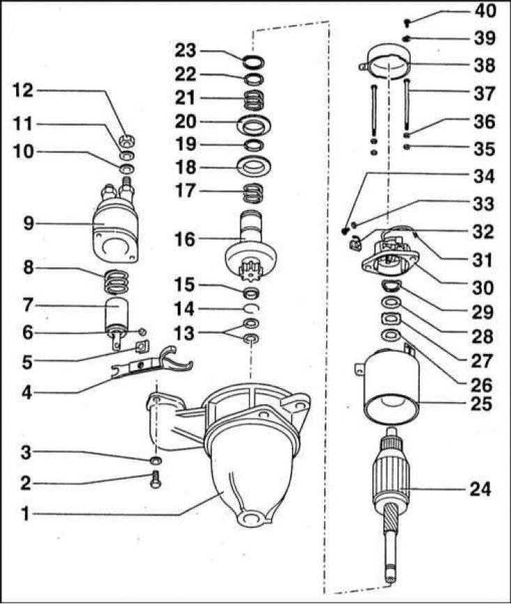
1 - Front cover; 2 - Mounting screw M6x16; 3 - Washer; 4 - Drive lever; 5 - Overlay; 6 - Pin; 7 - Relay anchor; 8 - Spring; 9 - Traction relay; 10 - Washer; 11 - Spring ring; 12 - Nut M10; 13 - Adjusting washer; 14 - Retaining ring; 15 - Retaining ring; 16 - Drive with overrunning clutch; 17 - Compression spring; 18 - Thrust washer; 19 - Sealing ring; 20 - Thrust washer; 21 - Compression spring; 22 - Washer; 23 - Retaining ring; 24 - Anchor; 25 - Housing with stator; 26 - Washer; 27 - Washer; 28 - Washer; 29 - Spring; 30 - Back cover; 31 - Connecting tape; 32 - Brush; 33 - Spring washer; 34 - Screw M4x6; 35 - Washer; 36 - Spring washer; 37 - Tie bolt M6x123; 38 - Protective cover; 39 - Spring washer; 40 - Screw M6x10
Magneton 1.0 starter section
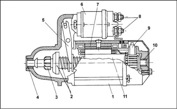
1 - Body; 2 - Overrunning clutch; 3 - Drive gear; 4 - Plain bearing; 5 - Lever; 6 - Traction relay; 7 - Stator; 8 - Main contacts; 9 - Brush; 10 - Plain bearing; 11 - Anchor
Starter wiring diagram
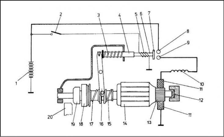
1 - Battery; 2 - Ignition switch; 3 - Return spring; 4 - Plunger; 5 - Winding; 6 - Retractable rod; 7 - Contact pad; 8 - Main contact; 9 - Main contact; 10 - Excitation winding; 11 - Brushes; 12 - Brake washers; 13 - Collector; 14 - Anchor; 15 - Spring; 16 - Lever; 17 - Spring; 18 - Overrunning clutch; 19 - Drive gear
Starter Magneton 0.8 with planetary gear
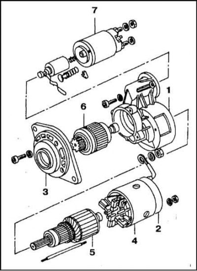
1 - Body; 2 - Back cover; 3 - Front cover; 4 - Stator; 5 - Anchor; 6 - Planetary gear; 7 - Traction relay
General information
The starter is a DC electric motor that, through a reduction drive, turns the crankshaft at the moment the engine starts.
Until July 1995, all models were equipped with a Magneton starter with a power of 1 kW, from that moment on, the 1.3 l models began to be equipped with a Magneton 0.8 starter, which is distinguished by smaller weight and size characteristics with increased torque. Both starters have the same mounting dimensions and are fastened with two M8 bolts.
The starter is attached to the clutch dome. The starter drive pinion is engaged with the flywheel ring gear by means of a traction relay.
The old Magneton 1.0 starter consists of a housing, front and rear covers, anchor, overrunning clutch and traction relay. The starter housing is fastened to the front and rear covers with two through bolts.
Inside the housing, steel cores are fixed, onto which the excitation windings are wound. To ensure the possibility of flowing large starting currents, the excitation windings are made of copper tape.
The anchor consists of a shaft onto which a core is pressed, consisting of separate magnetic plates insulated from each other. The plates have groove-shaped cutouts. Rotor windings are laid inside the grooves. Both ends of the windings are brought out to the collector.
The collector is located at one end of the anchor shaft and consists of copper plates, also insulated from each other. The anchor shaft ends with journals of friction bearings, the bushings of which are seated in the housing and rear cover of the assembly.
On the opposite side of the shaft there are spiral splines on which the overrunning clutch assembly with the drive gear is mounted. When the traction relay is triggered, the gear shifts along the shaft splines until it engages with the flywheel ring gear.
The back cover of the housing contains four brushes fixed in brush holders. The brushes are pressed against the collector by a spiral spring. A protective tin casing is fixed to the cover by means of an M6 bolt, protecting the collector and brushes from contamination.
The electromagnetic traction relay is mounted in the starter front cover assembly and secured in it with two M6x16 bolts. The relay performs two functions: it sets in motion the lever of the mechanism for engaging the pinion with the flywheel ring gear, and also closes the feed circuit
The traction relay consists of a housing with a winding inside. A movable plunger made of a material with high magnetic permeability is inserted inside the winding. The plunger is connected to the starter drive lever. The plunger is returned to its original position using a special spring. A rod with a copper movable contact fixed to it is inserted into the plunger hole, closing the main contacts, which are the heads of two bolts directly connected to the battery terminals.
When the ignition key is turned to position II, the current from the battery begins to flow through the winding of the contact rod. The resulting magnetic field draws the plunger into the relay assembly. The movement from the plunger is transmitted to the lever attached to it, which in turn moves the drive assembly along the spiral splines of the starter armature shaft toward the flywheel ring gear.
At the moment of closing the main contacts, current begins to flow through the starter winding and the drive gear, which is engaged with the teeth of the flywheel ring gear, spins the engine crankshaft. If the teeth of the gear and the ring gear are not engaged with each other at the initial moment, then such engagement will invariably occur under the influence of the spring (17) developed at the moment of alignment of the gear teeth with the gap between the teeth of the flywheel ring gear.
Due to the fact that when the gear is engaged with the crown, it also has a translational movement, the initial jerk from the impact of the teeth is softened.
As soon as the engine starts and the flywheel speed begins to exceed the drive gear speed, the overrunning clutch will begin to rotate freely on the armature shaft, thereby protecting the starter from destruction.
When the ignition key is released, the magnetic field of the contact rod coil disappears and the plunger of the traction relay returns to its original position under the influence of the force developed by the spring. In this case, the main contacts open and the power supply to the starter is disconnected. The drive lever also returns to its original position and the pinion disengages from the flywheel ring gear. Due to the spiral shape of the guide pins on the armature shaft, the disengaged flywheel pushes the pinion back. The drive lever slightly compresses the spring (15), which presses the armature assembly against the brake disc (12).
The new Magneton 0.8 starter is equipped with a planetary gearbox. When switched on, the starter anchor begins to rotate at a frequency of 5000 rpm, due to which relatively high power is developed. In the planetary gearbox, the speed decreases with a simultaneous increase in torque, which guarantees trouble-free starting of a cold engine even in frosty weather.
Removal and installation of both types of starters is carried out in a similar manner.
Removal
1. Disconnect the negative battery cable - this is especially important as the starter power cable is constantly live.
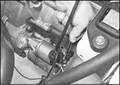
2. Remove the rubber protective cover and disconnect the wiring from the back of the traction relay. Try to remember the order in which the wires are connected.
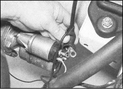
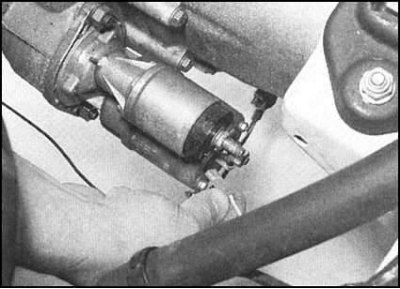
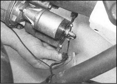
3. Release the lock, separate the reverse light wiring from the starter housing and move it to the side.
Note: The reverse light wiring may need to be disconnected from its switch sensor to ensure there is no risk of damage to it when removing the starter.
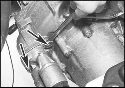
4. Supporting the starter with your hand, loosen the mounting nuts on the clutch dome.
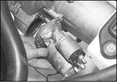
5. Remove the starter.
Installation
Installation is carried out in the reverse order. Tighten all fasteners with the required force. Ensure that the wiring is laid correctly and connected securely.