
Scheme of the ignition system with a non-contact sensor-distributor
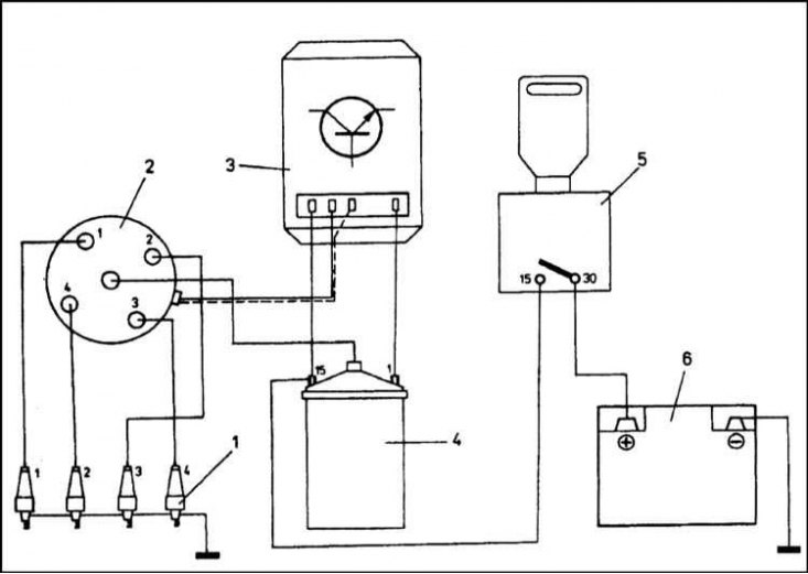
1 - Spark plugs; 2 - Ignition distributor; 3 - Switch; 4 - Ignition coil; 5 - Ignition switch; 6 - Battery
Note. Bosch Mono-Motronic, Simos 2P and Magneti-Marelli 1AV systems are subsystems of a single engine management system that controls power supply and fuel ignition order. This Part of the Chapter is devoted only to components related to ignition.
Carburetor models
The ignition system is designed to convert the low voltage current coming from the battery or generator into a high voltage current, as well as to supply this explosive voltage at the appropriate times to the spark plugs that ignite the air-fuel mixture in the engine cylinders.
On the carburetor models of the cars in question, an ignition system with a non-contact sensor-distributor and a switch is used. A diagram of such an ignition system is shown in the illustration.
In the LV circuit of the ignition system, current flows through the contacts of the ignition switch to the terminal "15" ignition coils, and then - from the terminal "1" coils to the switch.
In the HV circuit, induced in the secondary winding of the ignition coil (is created at the moments of current interruption in the primary winding of the coil) current flows to the central terminal of the distributor cap and, then - through the slider and BB wires - to the spark plugs.
Bosch Mono-Motronic and Magneti-Marelli 1AV
Both systems include four spark plugs, five explosive wires, an ignition distributor, an electronic ignition coil, an electronic control unit (ECU), as well as a set of information sensors, actuators and connecting wiring. The schemes for placing the components of the systems are somewhat different, however, according to the principle of functioning of the system, they are almost identical.
The ECU provides a reference voltage to the input stage of the ignition coil, energizing the coil's primary winding. Periodically, the reference voltage is interrupted by the ECU, which leads to the folding of the magnetic field of the primary winding and the generation of HV voltage in the secondary. Further, the high voltage created in the coil is fed through the distributor along the BB wires to the spark plugs, which generate a powerful spark at the ignition stroke of the piston of each of the cylinders. A spark is formed between the spark plug electrodes at the moment an explosive voltage is applied to it and ensures guaranteed ignition of the air-fuel mixture injected into the cylinder. The ignition timing and the duration of the closed state of the interrupter contacts are determined and controlled by the ECU based on the information from the sensors of the engine management system about the engine speed, the position of the crankshaft and the depth of depression in the intake manifold. Other parameters that affect the choice of ignition timing include the position and speed of the throttle valve, the temperature of the intake air and coolant, and in the Magneti-Marelli system, also the detonation of the air-fuel mixture (information is sent to the ECU from the relevant sensors).
Air-fuel mixture knock control is available on 1.6L models equipped with the Magneti-Marelli 1AV injection system. The knock sensor is mounted on the cylinder block and, by increasing vibrations, detects the moment when the ignition becomes too early. Having received information from the sensor in a timely manner, the ECU retards the ignition, preventing the occurrence of knock-related sound effects. Next, the ECU in several stages returns the ignition timing to the normal value. In the event of re-occurrence of detonation, the cycle repeats.
Idle speed control is carried out partly by means of an electronic throttle position module installed in the wall of the throttle body, and partly by the ignition system by timely adjustment of the ignition timing. In view of the foregoing, there is no need for manual speed adjustment, and the possibility of its implementation by the system design is not provided.
In some systems, the ECU is able to organize multiple ignition when starting a cold engine. When the engine is cranked by the starter, the spark plugs produce a spark many times on each stroke, which significantly increases the efficiency of ignition of the mixture and makes it easier to start the engine.
It should be noted that the diagnostics of system malfunctions described in this Chapter is possible only with the use of special electronic equipment. If you identify the cause of the failure during the implementation of the listed in Section Diagnostics of malfunctions of system of ignition and check of a condition of its components this Chapter of checks fails, the car should be driven to a service station. Descriptions of the procedures for removing and installing failed components are given in the relevant Sections of the Chapter.
Simos 2P
Simos 2P uses static ignition (without distributor). The ignition system consists of two ignition coils enclosed in casings and combined into a single module. The model is installed directly above the spark plugs, and therefore no BB wires are provided.
Each of the coils of the module serves two cylinders (one - 1st and 4th, the second - 2nd and 3rd).
According to the commands issued by the ECU, the coils generate two ignition sparks in the cylinders - one on the compression stroke and one on the exhaust stroke. The breakdown voltage of the spark plug on the compression stroke as a result of the increase in pressure is very significant. On the exhaust stroke, when the compression is negligible, a very weak spark is generated that has no effect on the exhaust gases released from the cylinder and is called idle. This ignition scheme avoids the need to install a separate coil for each of the candles.
The ECU controls the functioning of the system based on the signals received from various information sensors. Based on the incoming information about the engine temperature, current load and speed, the ECU determines the parameters for correcting the ignition timing and coil charging time. at idle, the ECU, by adjusting the ignition timing accordingly, changes the engine torque in order to maintain rpm stability. The system functions in close contact with the throttle position potentiometer.
The ignition system also includes a knock sensor. Installed at the rear of the cylinder block, the sensor responds to a change in the engine vibration frequency and determines the moment when the mixture starts to detonate in the cylinders. Based on the information received from the sensor, the ECU makes timely step-by-step adjustments to the ignition timing, preventing further detonation development.