
Longitudinal section of the generator
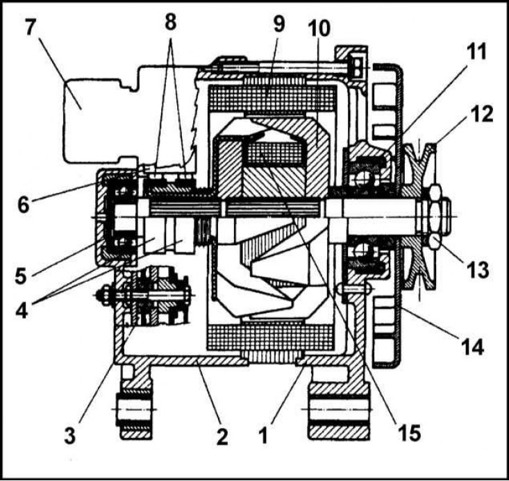
1 - Front cover; 2 - Back cover; 3 - Board with diodes; 4 - Contact rings; 5 - Rear bearing; 6 - Brush holder; 7 - Voltage regulator; 8 - Brushes; 9 - Stator with windings; 10 - Rotor; 11 - Front bearing; 12 - Pulley; 13 - Nut; 14 - Impeller; 15 - Rotor winding
Generator winding connection diagram
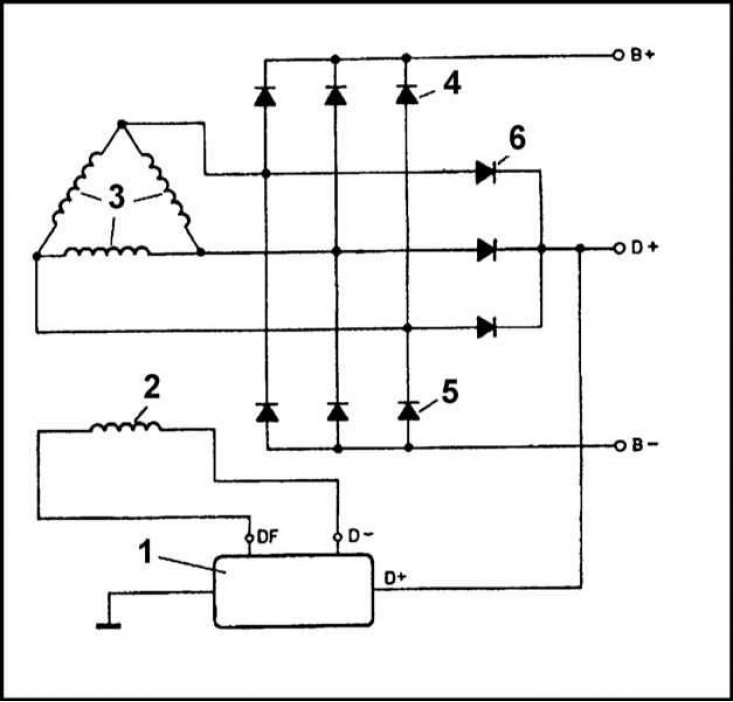
1 - Voltage regulator; 2 - Excitation winding; 3 - Stator winding; 4 - "Positive" rectifier diodes; 5 - "Negative" rectifier diodes; 6 - Excitation winding diodes
The vehicles in question use a synchronous alternator with a built-in rectifier.
In principle, all generators used for completing (see specs) arranged in the same way. A partial longitudinal section of the generator is shown in the illustration, the winding connection diagram is shown in the illustration below.
The generator housing consists of two covers (front and back), fastened with three long through bolts M5. The stator is fixed inside the housing. Three wire windings connected by a triangle are wound on insulated metal stator plates. The stator windings are connected to nine silicon rectifier diodes placed on boards and brackets inside the generator housing. Diodes rectify the alternating current generated in the windings.
In both covers of the generator housing, a ball bearing is placed in which the rotor shaft is seated. Magnets are fixed on the rotor shaft with a characteristic "beak-shaped" forms covering the excitation winding. Slip rings are installed on the same shaft. The rings are isolated from the shaft and connected to the terminals of the excitation winding.
Spring-loaded carbon brushes rest against slip rings. One of the 5 brushes is connected to the D+ terminal, the other to the D- terminal. The wires from both terminals are brought out through the back cover. When the ignition is turned on, when the engine has not yet been started, the following electrical circuit is energized: positive battery terminal - ignition switch contacts - control lamp - voltage regulator - generator excitation winding - ground. This turns on the control lamp in the instrument panel of the car.
Upon completion of the engine start, when the crankshaft speed exceeds 900 rpm, the generator is excited and begins to produce alternating current, which is then rectified by the diode assembly. At the same time, voltage appears at the D + terminal and, since there is no longer a potential difference on the control lamp, it goes out. Current is supplied to the excitation winding through three diodes (6) and voltage regulator. Diodes, called excitation diodes, work similarly to diodes (4) And (5), with the only difference that their load is only the field winding and the voltage regulator, which is why they are smaller in size and do not need heat sinks.
The current between the generator and the battery can only flow in one direction - from the generator to the battery. In the opposite direction, the diode rectifier assembly does not let it through.
The magnitude of the voltage generated by the generator is controlled by changing the excitation current in the rotor winding. This function is performed by the voltage regulator.
The pulley in the blower impeller is mounted on the rotor shaft with the help of an M14 lock nut.
The adjusting plate bracket for adjusting the tension force of the drive belt is attached to the cylinder head with the head mounting nut. The nut is screwed onto the M8x20 bolt.
Removing
1. Disconnect the negative cable from the battery.
2. Remove the accessory drive belt from the alternator pulley.
Models 1.3 l
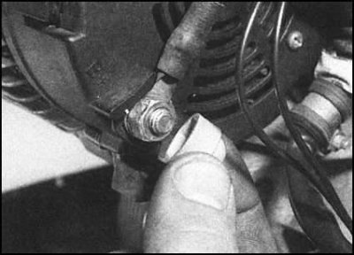
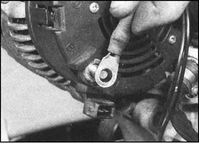
1. Remove the protective cap, remove the nut with washers and remove the power wire terminal from the generator terminal stud.
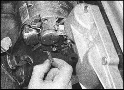
2. Disconnect the signal wire from the generator.
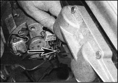
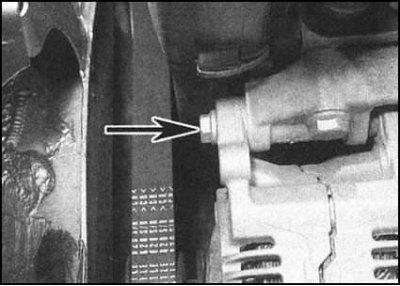
3. Give the bolt (s) generator top mount.
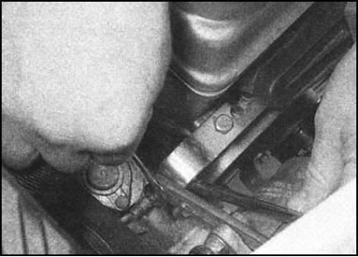 |  |
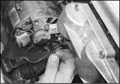
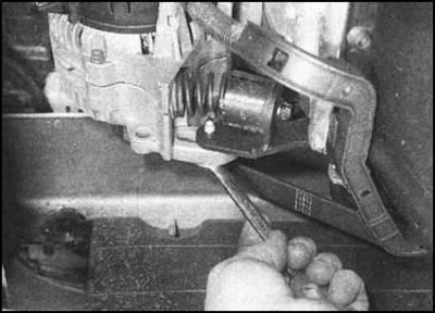
4. Loosen the bottom support bolt nut and rotate the alternator assembly towards the radiator to provide sufficient working space.
 | 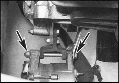 |
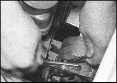
5. Turn out the bottom through bolt and remove the generator from a basic arm.
Diesel models and 1.6L models
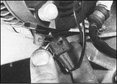
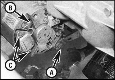
1. Disconnect the signal wire connector on the generator.
2. Remove the protective cap, give the nut, remove the washers and disconnect the power wire terminal from the generator.
 |  |
3. Turn out bolts of the bottom and top support of the generator, then remove the generator from the arm. If equipped, rotate the alternator drive belt tensioner pulley outward to gain access to the lower support bolt.
 |  |
All models
If there is a need to remove the brush holder / voltage regulator module, refer to the materials of Section Replacing the Brush Holder/Voltage Regulator Module.
Installation
1. Installation is carried out in the reverse order. Track correctness of a laying and adjustment of a tension of a driving belt.
2. Tighten all fasteners to the required torque.