
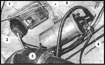
Ignition Distributor Components
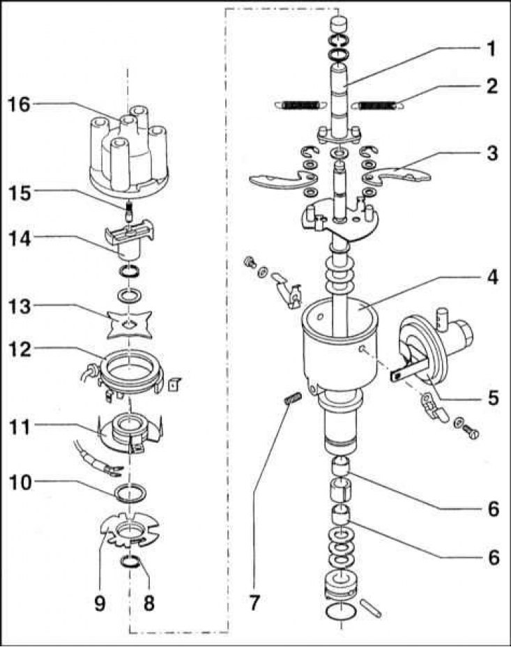
1 - Rotor bushing; 2 - Spring; 3 - Counterweight of the centrifugal regulator; 4 - Housing; 5 - Membrane mechanism of the vacuum corrector; 6 - Bearing; 7 - Screw M6x8; 8 - Retaining ring; 9 - Base plate; 10 - Spacer washer; 11 - Turning plate; 12 - Pulse sensor coil - "G173"; 13 - Rotor; 14 - Runner; 15 - Brush; 16 - Lid
Note. The information given in this subsection applies only to systems with an ignition distributor.
During vehicle maintenance, do not check for voltage at electrical connections by shorting the wires to ground. Do not disconnect the BB wire from the ignition coil to the distributor while the engine is running or cranking. Do not disconnect the body of the electronic unit from the ground. Do not use diagnostic tools that can cause a short circuit in the LV circuit of the coil. Be careful with the wiring connecting the distributor to the switch.
Design features of the distributor and the principle of operation of the ignition regulators
The ignition distributor provides the necessary sequence of pulses to the spark plugs; generates voltage pulses, which are then sent to the ECU and control the interruption of current in the primary winding of the ignition coil.
The main components of the distributor are: a generator of electrical impulses, a voltage separation circuit in the secondary circuit; centrifugal regulator and vacuum ignition advance corrector.
The distributor drive is carried out from a gear put on the axle, which is engaged with the gear of the crankshaft. The frequency of rotation of the axis of the drive gear is two times lower than the frequency of rotation of the crankshaft.
The housing of the ignition distributor is closed from above with a cover, which is fastened by means of two spring clips. The housing flange is designed to fix the position of the distributor.
The cover is made of a non-conductive material that can withstand high electrical loads, equipped with five terminals enclosed in the sockets of the protrusions of the cover. The wires of the BB circuit of the ignition system are connected to the terminals.
The BB wire from the ignition coil is connected to the central terminal of the distributor cap. The terminal itself is connected to the distributor runner by means of a spring-loaded carbon contact.
The remaining four candle terminals are directly connected to brass contacts pressed into the inside of the cover.
Near one of the terminals, a long vertical convex mark is applied to the distributor caps from the outside. The BB wire of the spark plug of the first cylinder is connected to this terminal.
The distributor shaft is fixed in the distributor housing by means of two self-lubricating bushings. A shank is provided in the lower part of the shaft, and a sleeve is installed on the upper part, into which the slider is inserted. In the upper end of this sleeve there is a groove that guarantees the unambiguous installation of the slider.
The slider is made of a dielectric material. Two brass plates are pressed into it from above, between which there is a resistor designed to suppress radio frequency interference. The plate, installed in the central part of the slider, is connected to the central terminal of the distributor cover by means of a carbon brush. Thanks to this design, the HV voltage from the ignition coil through the noise suppression resistor is connected to the second brass plate, fixed on the nose of the runner and, when the engine is running, alternately comes into contact with the candle terminals of the distributor cover.
Magnetic induction sensor (Hall Sensor) consist of a 4-pole rotor, a ring with pole cores and an induction coil. As the rotor rotates, the magnetic field lines are periodically interrupted. A change in the magnetic field leads to the generation of pulses in the winding of the induction coil. Further, these pulses enter the ECU, which controls the passage of HV voltage through the ignition coil.
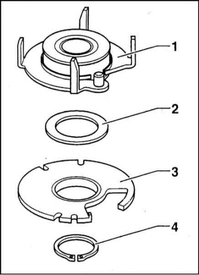
1 - Turning plate; 2 - Spacer washer; 3 - Base plate; 4 - Retaining ring
The centrifugal regulator corrects the ignition timing depending on the crankshaft speed, regardless of the amount of engine load. The principle of operation of the regulator is based on the use of centrifugal force acting on special counterweights. The regulator consists of a plate fixed on the distributor shaft, to which two pins are riveted. Two counterweights are loosely placed on the pins, pulled together by springs. A bushing is fixed on the upper part of the distributor shaft, the base of which is a plate with anchors for fastening the opposite ends of the springs and pins included in the grooves of the counterweights. The rotor of the inductive sensor is mounted on the bushing. The axial play of the distributor assembly is controlled by the selection of a combination of spacer washers (washers are available in thicknesses of 0.05, 0.10 and 0.16 mm).
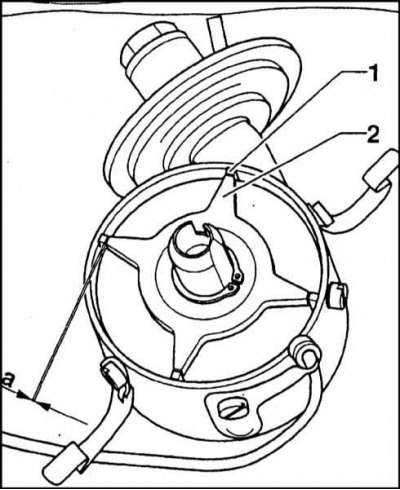
1 - Rotor tips; 2 - Rotary plate; a - The value of the air gap
The rotor parameter to be checked is the value of its air gap (A), which should be set closer to the upper limit of the allowable range (see specs).
With an increase in the frequency of rotation of the crankshaft, the counterweights under the action of centrifugal force diverge to the sides and, pressing on the pins of the movable plate, cause the rotor to rotate in the direction of rotation of the distributor shaft. Due to such a displacement of the rotor, the generation of pulses in the coil winding of the inductive sensor occurs with a certain lead, i.e. ignition becomes earlier.
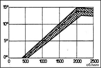
The characteristics of the springs, the mass and shape of the counterweights are selected in such a way as to obtain the design values of the ignition advance, depending on the specific engine speed. The illustration shows the operating characteristic of a centrifugal governor.
The vacuum corrector is designed to correct the ignition timing depending on the engine load (excluding turnovers). The corrector is attached to the distributor body by means of a bracket and two M4 screws. A membrane diaphragm is placed in the inner chamber of the vacuum corrector, which is pressed by a spring in the direction of the distributor housing. The diaphragm is connected by a rod to the pole pieces of the induction sensor.
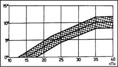
On the one hand, atmospheric pressure acts on the diaphragm, on the other hand, a vacuum is supplied, which occurs due to the fact that the space inside the housing is connected by a hose to the engine exhaust manifold. With increasing load, the throttle valve opens to a greater extent, which leads to an increase in the depth of vacuum in the pipeline. Under the influence of the pressure difference, the diaphragm bends towards the distributor body, while overcoming the resistance of the spring. The rod connecting the diaphragm to the plate, on which the ring with pole pieces is located, causes the latter to rotate in the opposite direction to the direction of rotation of the distributor shaft. In this case, the ignition timing is shifted forward and the ignition becomes earlier. When the load decreases, the depth of vacuum decreases and the spring bends the diaphragm in the opposite direction, making the ignition later. The performance of the ignition timing vacuum corrector is shown in the illustration.
Thanks to the combined action of both regulators, the necessary setting of the ignition timing is ensured at any engine speed and load.
The ignition distributor is connected to the switch with a shielded wire so that the transmitted impulses do not distort the characteristics of electromagnetic fields and thereby cause malfunctions of the switch.
The switch generates the amplitude and duration of voltage pulses in the ignition coil.
The switch does not require regular maintenance. It is enough just to take care of a reliable connection of the case to the ground (is controlled by the reliability of tightening the right lower screw of the housing fastening).
To protect the wire lugs from corrosion, which increases the resistance of contact connections, a thin layer of acid-free vaseline should be applied to the surface of the lugs, or they should be sprayed with a special preservative composition. Access to the contact terminals is opened after removing the rubber protective cover. Don't forget to reinstall the cover when assembling.
When reconnecting the wire ends to the contacts of the electronic unit, it is necessary to ensure that they are connected correctly.
The control of the elements of the ignition system should begin with checking the reliability of connecting the electrical connector to the ignition switch. In addition, it is necessary to check the reliability of the grounding of the switch chassis.
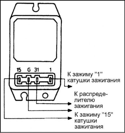
To check the power supply to the ignition system, turn on the ignition without starting the engine, and using a voltmeter or probe lamp, make sure that there is voltage at terminal 15 of the switch and terminal 15 of the ignition coil. To check the voltage at terminal 15 of the switch, disconnect the connector from the unit. If the check is made with a voltmeter, you can also check the voltage at terminal 1 of the coil. The result must not be more than 0.3 V less than the reading taken at terminal 15. Otherwise, check the resistance of the primary winding of the coil (nominal value is 0.6 ohm).
If there is no voltage at terminals 15, it can be connected in an emergency way by connecting the terminal with a jumper to the positive pole of the battery.
Checks should be made quickly, since at the same time the heating coil in the carburetor automatic start-up device is turned on, the edges can easily burn out.
Removing
1. Disconnect the negative cable from the battery.
2. Bring the engine to TDC.
3. If necessary, disconnect the BB wires from the distributor cap (don't forget to label them first)
Note. It is preferable to remove the cover with wires connected to it. It is better to transfer the wires to a new cover in order to avoid violating the ignition order one by one.
Bosch Mono-Motronic system
1. Release the fasteners, remove the cover from the distributor and take it to the side together with the connected BB wires.
2. Mark the position of the base of the distributor assembly in relation to the engine block.
3. Removal and installation of the distributor can be done in one of two ways: either assembled with an extension pipe, or separately from it. Preference should be given to the latter method.
4. For removal of the distributor in gathering with an extension pipe give two bolts of fastening of the last to a forward cover of the engine. Now the assembly can be removed.
5. When the distributor shaft drive gear disengages from the helical camshaft drive gear, the slider will inevitably turn. Immediately mark the final position of the slider so that the assembly can be returned exactly to its original position during installation.
6. To disconnect the distributor from the extension pipe, mark the relative position of the components, then loosen the tie bolt nut and disassemble the assembly.
7. Try not to rotate the distributor shaft and the engine crankshaft when the distributor is removed.
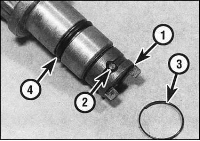
8. Remove the O-ring from the groove in the distributor housing.
Note. During assembly, the sealing ring must be replaced without fail.
Magneti-Marelli 1AV system
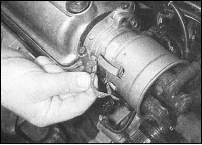
1. Disconnect the ground bar from the metal shielding cover.
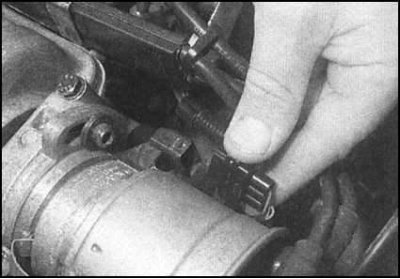
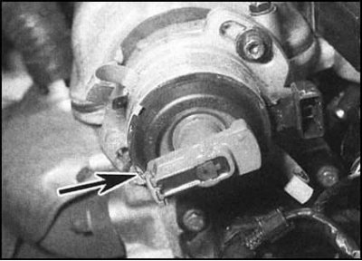
2. Disconnect the electrical connector of the Hall sensor on the distributor housing.
3. Release spring clips,...
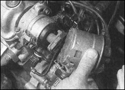
... remove the cover and lay it aside with the connected BB wires.
4. Make sure that the slider is turned with its nose to the BB terminal of the spark plug wire of the first cylinder on the distributor cap (the corresponding mark must be applied to the rim of the distributor housing).
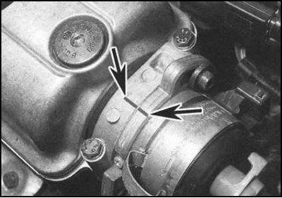
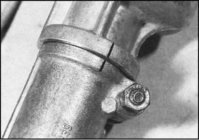
5. Use a scriber or marker to mark the position of the distributor body in relation to the support flange.
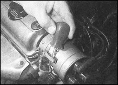
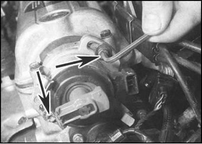
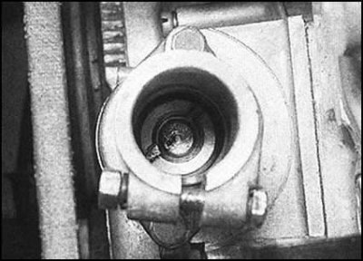
6. Turn out clamping bolts, then take the distributor case from a head of cylinders. It is possible that in order to release the large sealing ring, the distributor housing will have to be slightly shaken from side to side.
 | 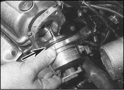 |
7. Remove the sealing ring from the lower end of the distributor housing and carefully inspect it. A worn or damaged ring must be replaced.
Installation
Bosch Mono-Motronic system
1. Make sure that the engine is still in the TDC position of the end of the compression stroke of the first cylinder. Correct the position of the distributor shaft so that the slider turns with its nose to the mark on the end part of the distributor housing rim. If the extension tube is left on the motor, make sure that the drive pawl fits into the groove on the extension shaft. When installing the distributor assembly with an extension tube, turn the slider to the position marked when removing the assembly.
2. Having achieved the alignment of the marks, install the distributor in its regular place. If necessary, slightly correct the position of the slider in order to engage the drive pawl or gear teeth.
3. Replace the distributor cap (make sure its orientation on the body is correct). If necessary, connect BB spark plug wires. Remember that the correct functioning of the engine is possible only if a certain ignition order is observed (1-3-4-2).
4. Connect the main BB wire coming from the ignition coil to the central terminal of the cover.
5. With careful installation of a new distributor, the ignition timing should not be greatly disturbed. However, it is wise to take the car to a workshop to ensure the warranty, where the correct ignition timing will be checked using the appropriate special equipment.
Magneti-Marelli 1AV system
1. Make sure that the engine is still at the TDC position of the end of the compression stroke of the first cylinder. Install the distributor by inserting the drive pawl into the receiving hole in the camshaft drive flange and loosely screwing in the hold-down bolts. The slider should be turned with its nose towards the mark of the position of the BB terminal of the wire of the spark plug of the first cylinder on the cover - the corresponding risk is applied on the rim of the housing.
2. Replace the distributor cap. Track reliability of a snap-in of spring clamps.
3. Connect the Hall sensor wiring.
4. Connect the ground bar.
5. Alternately connect the candle wires of the candles to the terminals of the BB cover. Remember to follow the required ignition order (1-3-4-2).
6. Connect the main BB wire coming from the ignition coil to the central terminal of the distributor cover.
7. With careful installation of a new distributor, the ignition timing should not be greatly disturbed. However, it is wise to take the car to a workshop to ensure the warranty, where the correct ignition timing will be checked using the appropriate special equipment.