
Scheme of the engine lubrication system
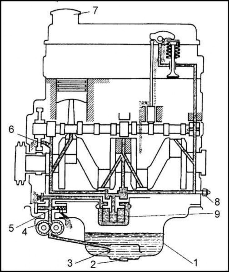
1 - Oil pan; 2 - Oil drain plug; 3 - Oil intake; 4 - Oil pump; 5 - Pressure reducing valve of the pump; 6 - Holes for lubricating the camshaft drive chain; 7 - Filler neck; 8 - Oil pressure switch; 9 - Oil filter
Oil pump
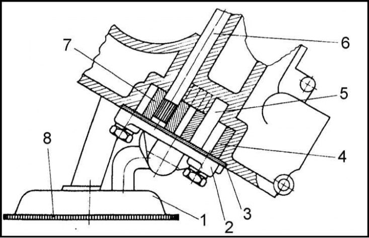
1 - Oil intake; 2 - Cover; 3 - Gasket; 4 - Driven gear; 5 - Axis of the driven gear; 6 - Pump shaft; 7 - Drive gear; 8 - Mesh filter of the oil intake
Pressure reducing valve (side cut)
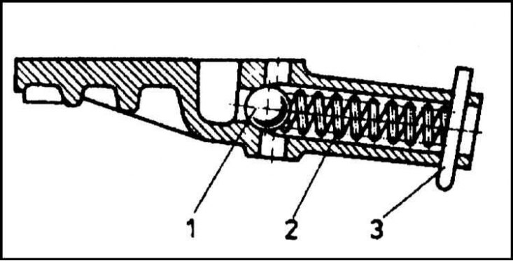
1 - Ball; 2 - Spring; 3 - cotter pin
Full flow oil filter
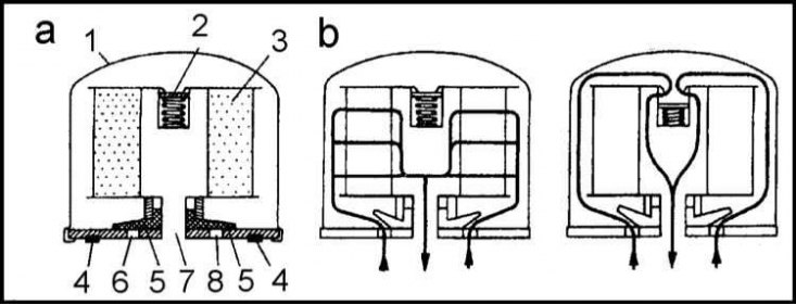
a - Section; b - The principle of operation of the safety valve; 1 - Housing; 2 - Safety valve; 3 - Filter element; 4 - Gasket; 5 - Anti-drainage valve; 6 - Inlet holes; 7 - Outlets
Lubrication system - general information
The task of the lubrication system is to reduce the friction component between the internal components of the engine, protect them from corrosion, and also remove excess heat from the parts. The scheme of the lubrication system is shown in the accompanying illustration.
The circulation of oil in the engine is as follows. The oil pump draws oil through the oil pick-up from the crater pan and supplies it through a special channel to the full-flow oil filter. After filtering, the oil is fed into the main oil line and flows to the crankshaft and holes in the block in which the camshaft journals rotate. Through the channels provided inside the body of the crankshaft, oil enters the connecting rod bearing shells.
Oil is also supplied from the main oil line to the oil pressure switch. Through the holes in the rocker arms, oil is sprayed onto the valve stems.
Through the holes in the upper part of the lower head of the connecting rods, oil is sprayed onto the surface of the cylinders. The oil supply to the timing chain is through holes in the front of the cylinder block.
The oil filler neck, cylinder head covers are closed with a plastic plug equipped with a rubber sealing ring.
The hose of the crankcase ventilation system is connected to the fitting on the side wall of the neck.
The oil pan is stamped from steel sheet. A sealing gasket is installed between the pallet and the cylinder block.
The pallet is fixed to the block by means of nineteen M6x20 bolts, which should be tightened with a force of 7 ÷ 9 Nm in a strictly defined order.
At the bottom of the pallet there is a drain plug with M16x1.5 thread. the plug is equipped with an aluminum sealing washer 16x22 in size.
The oil pump is located at the bottom of the timing chain cover. The pump is driven by a gear mounted on the ignition distributor shaft. The pump draws oil through a strainer-equipped oil pick-up from the crater pan.
The illustration shows the components of the oil pump assembly. The driven gear is mounted on an axle pressed into the timing chain cover. The pump shaft is threaded through the hole in the cover, on the bottom of which the drive gear is installed. A groove is provided in the upper part of the shaft, designed to engage the shaft with the ignition distributor drive shaft.
The driven and driving gears are engaged with each other in such a way that, during rotation, oil is sucked in and forced into the engine line. The height of the oil pump gears is 20mm.
From below, the pump assembly is closed with a lid, fixed with four M6x20 bolts, also threaded through the sealing gasket.
The gasket, in addition to sealing the joint, also acts as a limiter for the axial play of the gears. If during the repair it is found that the factory gasket is missing, it can be made from a paper sheet with a maximum thickness of 0.1 mm.
If the gap between the cover and the ends of the shaft gears lies within 0.045 ÷ 0.158 mm, the gasket can not be installed at all.
An excessive increase in pressure in the engine is resisted by a pressure reducing valve installed in the oil pump cover. The main working element of the valve is a ball with a diameter of 12 mm. The ball is pressed against its seat by a spring. The other end of the spring rests on the cotter pin. When the oil pressure exceeds 4 kgf/cm2, the spring is compressed and the ball slightly moves away from the seat. The excess oil then drains back into the oil pan.
From the pump, oil under pressure enters the full-flow oil filter. Oil enters the filter housing through the inlet openings, after depressing the drain valve. After passing through the paper filter element, the oil enters the engine galleries through the filter inlet.
The drain valve is made of rubber or plastic and further prevents oil from returning to the pump. Thanks to this filter design, the pressure in the system rises immediately after starting the engine. When installing a new filter, it takes some time to fill it with oil, which determines the delay in turning off the corresponding warning lamp on the car's dashboard.
The safety valve ensures that oil bypasses the filter element in the event of a blockage of the latter, thereby preventing excessive pressure build-up. The valve is also triggered by an excessive increase in pressure when using oils with a high degree of viscosity used in the winter season. As the engine warms up and the oil viscosity decreases, the valve gradually returns to the closed position. In general, the filter is designed and manufactured to withstand pressures up to 15 kgf/cm2.
Inside the filter housing is a filter element made of specially processed paper. The paper is folded like an accordion and stacked in the form of a star, so that a large filtering surface can be accommodated in a relatively small body.
The junction of the filter housing with the seating surface on the cylinder block is sealed with a rubber or plastic sealing gasket seated in a special groove in the filter base.
The oil pressure switch, by turning on the control lamp, informs the driver about the drop in oil pressure in the lubrication system below the permissible limit (0.3÷0.6 kgf/cm2).
Removing
Oil Pump Assembly Components
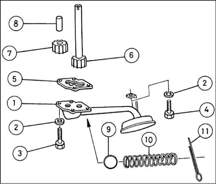
1 - Oil intake equipped with a strainer; 2 - Spring washer; 3 - Bolt for fastening the oil intake to the cover of the gas distribution chain; 4 - Bolt for fastening the oil intake to the main bearing cap; 5 - Sealing gasket (if provided); 6 - Pump drive gear; 7 - Driven gear of the pump; 8 - Axis of the driven gear; 9 - Reducing valve ball; 10 - Pressure reducing valve spring; 11 - Cotter pin
1. Remove the engine oil pan (see Section Removal and installation of the pallet crankcase of the engine).
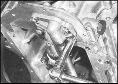
2. Loosen the four bolts securing the oil pickup housing with strainer to the underside of the timing chain cover...
..and one bolt securing it to the central main bearing cap. Carefully remove the oil pickup.
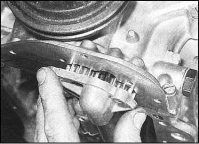
3. The gears can be removed by removing the oil pickup cover. If equipped, remove the seal (during assembly, it must be replaced without fail).
Status check
1. Check gears and pump housing for signs of wear and mechanical damage (type of chipped teeth).
2. If you have the necessary equipment, by measuring the gaps, evaluate the amount of wear on the gear axles and the pump housing (see specs).
3. In case of detection of damage, and also if the clearance exceeds the allowable values specified in the Specifications, the pump gears must be replaced as an assembly with the front cover of the timing chain with the pump housing mounted in it. The procedures for removing and installing the chain cover are described in Section Removal and installation of a head of cylinders in gathering with the inlet pipeline and a final collector.
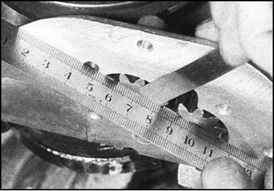
4. Temporarily install the gears into the pump housing, then use a flatness tester to (ribs of steel ruler) and a blade-type feeler gauge, measure the gap between the ends of the gears and the pump cover. Vehicle manufacturers (Skoda company) insist that the gap should not exceed 0.1 mm. If the clearance is close to the limit value, the oil pickup housing should be installed without a gasket. If the gap is too small, it can be corrected by selecting a gasket of the appropriate thickness. Exceeding the permissible value is evidence of component wear (housings and/or gears); in this case, the pump assembly must be replaced.
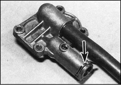
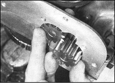
5. Remove the cotter pin from the oil pickup housing,
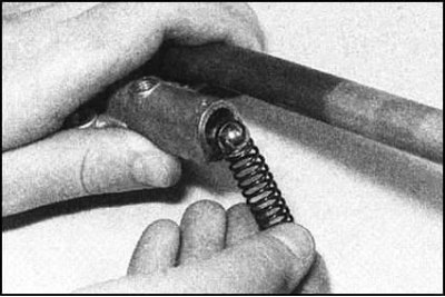
..then shake the spring and ball out of the pressure reducing valve seat. Check the removed valve components for signs of wear and mechanical damage. Planting a new ball into the valve seat is carried out with a hammer and a suitable soft metal drift - try to achieve a tight pressing of the ball to the valve seat. Insert the spring into the seat and secure the assembly with a new cotter pin.
Installation
1. Assembly is carried out in the reverse order. Use grease to temporarily secure the new gasket to the mating surface of the oil pickup housing.
2. Having generously lubricated, fill the gears with their axles into the pump housing. While holding the gears, press the oil intake housing against the mating surface, screw in the five mounting bolts and tighten them with the required force.
3. Reinstall the engine oil pan (see Section Removal and installation of the pallet crankcase of the engine).