
Note: See Warnings given in Chapter 1 of this section before starting work.
Health check
Fan thermal switch
1. Perform a Quick Circuit Breaker Test (see previous chapter). If the switch is to be replaced or more carefully checked, it must be removed.
2. To perform an exhaustive health check on the switch, connect a multimeter to the switch with two spare wires (switched to resistance measurement mode) or a test circuit consisting of a battery and a 12 V lamp. Hang the switch on a piece of twine in a container of water and heat the water. Measure the water temperature with a thermometer. Do not let the switch and thermometer touch the sides of the container.
3. Switch contacts should close (that is, the lamp should light up or the device should show the presence of electrical conductivity), when the water reaches the operating temperature of the fan (listed in Specifications). Stop heating the water and let it cool; the circuit breaker contacts must open at the specified Specifications fan cut-off temperature.
4. If the switch is noticeably different from what is described, or if it does not work at all, replace it.
Coolant Temperature Gauge Sensor
5. Constant voltage to the coolant temperature gauge installed in the instrument panel is supplied from the instrument panel supply wire, the grounding part of its circuit is controlled by the sensor.
6. The sensor is screwed into the thermostat housing. It contains a thermistor - an element whose electrical resistance decreases in a certain pattern when it is heated. Thus, while the engine is not warmed up, the resistance of the sensor is high, respectively, the strength of the electric current passing through the pointer is small and the arrow of the device points to «cold» scale sector. If a component is defective, it must be replaced.
7. If the temperature gauge is out of order, check other devices first; if they don't work at all, check the dashboard power wire. If only the temperature gauge is faulty, check its serviceability as follows.
8. If the pointer stays in «cold» sector of the scale, disconnect the sensor wire and touch it to the cylinder head to ground. If the arrow deviates (ignition on), the sensor is defective and must be replaced. If the arrow remains stationary, remove the instrument panel (see Section 12) and check the electrical conductivity of the wire going between the temperature gauge and the sensor, as well as the power supply to the dial gauge. If the circuit is good and the pointer still does not work, the pointer itself is damaged and must be replaced.
9. If the pointer stays in the «hot» sector of the scale, disconnect the sensor wire. If the arrow returns to «cold» scale sector (ignition on), the sensor is defective and must be replaced. If the arrow does not move, check the rest of the chain as described above.
Removing
Fan thermal switch
10. Wait for the engine and radiator to cool, then drain the cooling system to the level of the switch (see section 1). Alternatively, unscrew the expansion tank filler cap to release any residual pressure and have a suitable plug ready to plug the switch hole while it is removed. If the latter method is used, be careful not to damage the radiator, and do not use crumbling material to make the plug - this will allow foreign particles to enter the radiator.
11. Disconnect the negative cable from the battery.
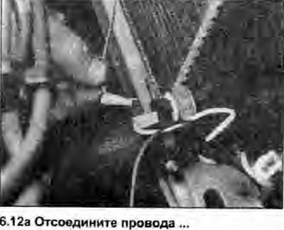
12. Disconnect the wiring connectors from the switch, unscrew the switch and remove it from the radiator (see photo).
 |  |
Coolant Temperature Gauge Sensor
13. Prepare to remove the component as described in step 10.
14. Disconnect the negative cable from the battery.
15. Disconnect the sensor wiring and unscrew the unit from the thermostat housing.
Installation
Fan thermal switch
16. When installing, replace the O-ring if it is worn or deformed (succinctly). Carefully clean the location of the switch in the radiator, then push the O-ring and the switch in there. Install the blocking ring and turn it to tighten gently. Connect the wires to the switch and battery, then fill the cooling system or check the coolant level if a plug was used (Section 1),
Coolant Temperature Gauge Sensor
17. When installing, apply a suitable sealant to the sensor threads. Connect the wires to the sensor and battery, then fill the cooling system or check the coolant level if a plug was used (see section 1).