
The layout of the main components of the lubrication system
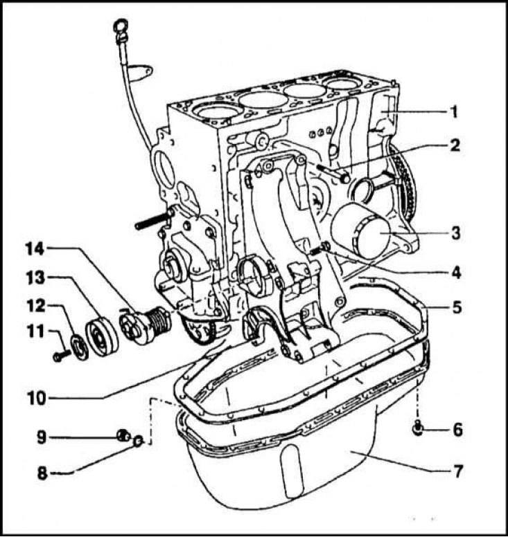
1 - Cylinder block; 2 - Bolt; 3 - Oil filter; 4 - Bolt; 5 - Sealing gasket; 6 - Bolt; 7 - Oil pan; 8 - Sealing gasket; 9 - Drain plug; 10 - Arm of the generator and the steering pump; 11 - Bolt; 12 - Washer; 13 - Roller; 14 - Tensioner
Oil pump components
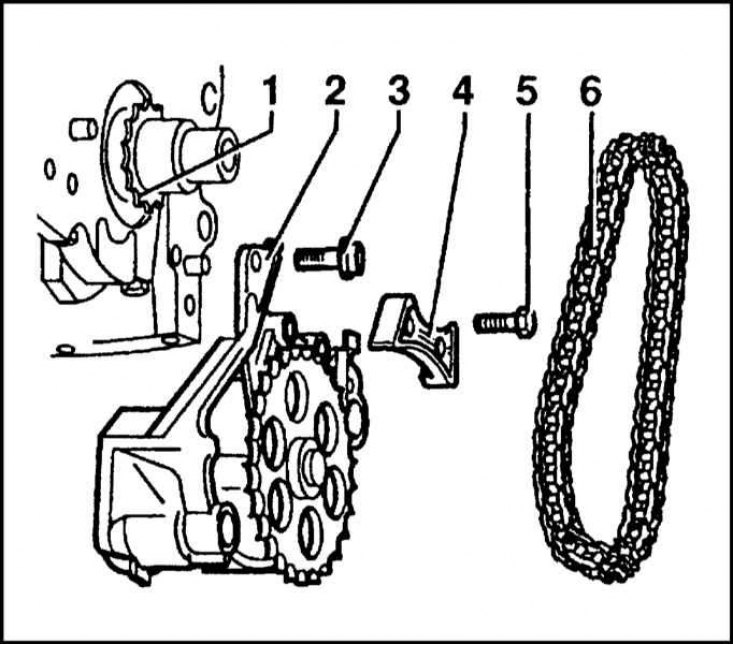
1 - Crankshaft gear; 2 - Oil pump; 3 - Mounting bolts; 4 - Guide bar (not available on all models); 5 - Bolts for fastening the guide bar; 6 - Drive chain
Lubrication system - general information
The lubrication system is combined, with a full-flow oil filter. The total amount of oil is 3.5 liters. The layout of the main components of the lubrication system is shown in the accompanying illustration.
The filler neck in the cylinder head cover is closed with a plug equipped with a sealing ring. The oil pan is cast from aluminum alloy and is connected to the cylinder block through a sealing gasket. The pallet is attached to the block by means of twenty bolts. The drain plug is machined in the form of a 19 mm hexagon turnkey.
The oil pressure switch is installed in the head of the block. The oil pressure indicator lamp on the instrument panel turns off when the pressure reaches 0.035 MPa. When checking the pressure in the system, it should not be lower than 0.2 MPa at an engine speed of 2000 rpm and an oil temperature of +80°C.
The gear oil pump is located at the front of the engine in the oil pan. An oil intake with a strainer is attached to the pump housing. A pressure reducing valve is mounted in the pump housing, which operates at a pressure of 0.4÷0.5 MPa. In case of failure, the oil pump is replaced as an assembly.
The replacement of a non-separable full-flow oil filter is carried out simultaneously with the change of impellent oil.
Removing
1.Remove the oil pan (see Section Removal and installation of the pallet crankcase of the engine).
2. Remove the front crankshaft oil seal with casing (see Section Replacing the crankshaft seals).
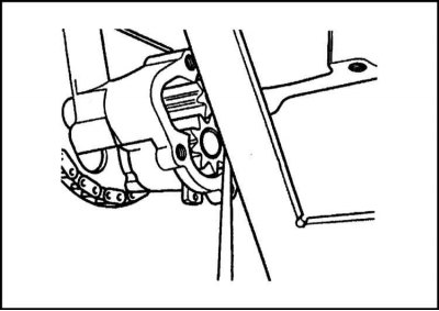
3. Turn out bolts of fastening of the pump to the block of cylinders.
4. Turn out bolts of fastening of an oil intake tube to an arm of the block of cylinders.
5. Remove the drive from the pump sprocket, then remove the pump assembly with the oil pickup from the engine.
Examination
1. Remove the screws from the connecting flange and remove the oil pickup tube and pump cover. If equipped, remove the O-ring.
2. Thoroughly clean the pump and check the condition of its gear teeth.
3. Assess the degree of wear of the drive chain. If there is significant play in the links and slack in the rollers, replace the chain.
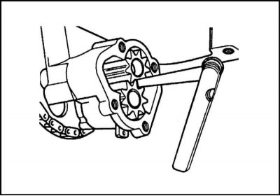
4. Using a blade-type feeler gauge, check the pump gear engagement play.
5. Check the axial play of the gears - use a flatness meter (edge steel) ruler and blade type probe.
6. Compare the results of the checks with the requirements of the Specifications. A worn pump must be replaced.
Installation
1. Install the oil pickup tube on the pump (don't forget to replace the o-ring). Tighten the fixing bolts to the required torque.
2. Put the chain on the pump drive sprocket and wind it on the crankshaft sprocket.
3. Screw in the bolts securing the pump to the engine block and tighten them until only by hand.
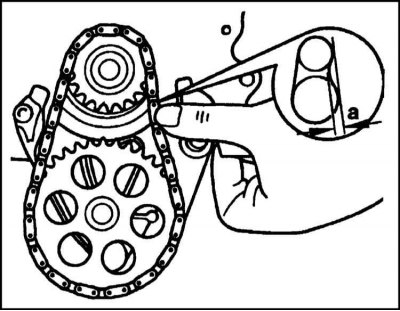
4. Wrap the chain by moving the pump in the bolt holes. Check the correct tension by measuring the chain deflection when pressing on it with your finger in the area in the middle between the sprockets. After adjusting the chain tension, finally tighten the pump mounting bolts.
5. Attach the oil pickup tube to the crankcase bracket.
6. Reinstall the crankshaft front oil seal with cover (Replace seal and cover gasket) - see Section Replacing the crankshaft seals.
7. Install oil pan (see Section Removal and installation of the pallet crankcase of the engine).