
Removing
1. Park your vehicle in a large, level, hard surface area.
2. Disconnect the negative cable from the battery.
Note. If your vehicle's stereo system is equipped with a security device, make sure you have the correct code to activate the audio system before disconnecting the battery.
3. Empty the cooling system and remove the spark plugs.
4. Remove the air cleaner with the components of the intake air path (see chapter Supply system). Remove the heated air supply hose from the air cleaner pipes and exhaust manifold housing plate.
5. Relieve residual pressure in the supply system (see chapter Supply system).
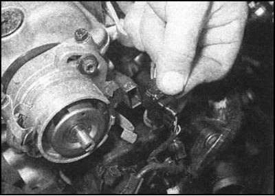
6. Remove the cover of the distributor with the BB wires connected to it, also remove the slider and the protective screen. It is not necessary to remove the cylinder head (it will be enough to disconnect the BB wire from the ignition coil), however, this will significantly expand the working space and facilitate access to the distributor.
7. If necessary, referring to the materials of Chapter 3, release the mounting collars and disconnect the hoses of the cooling path from the thermostat casing.
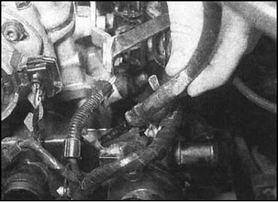
8. Disconnect the electrical wiring connectors of the following components:
- a) Knock sensor and λ-probe. Release both connectors from the bracket fixed above the flywheel;
- b) Intake air temperature/pressure sensor on the intake manifold;
- c) throttle control unit;
- d) Hall sensor from the ignition distributor;
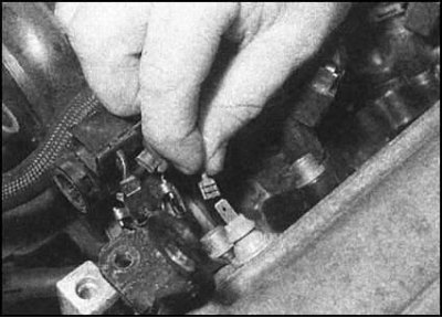
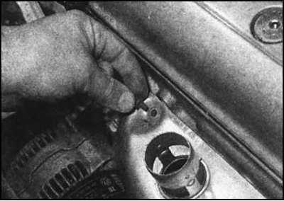
- e) Oil pressure switch on the rear wall of the cylinder head.
- f) Injector (ov) fuel and wiring harness on the intake manifold (if necessary, see chapter Supply system). Release the tourniquet from the intermediate clamps and set it aside);
- g) coolant temperature sensor (CTS) on the thermostat housing;
- h) After disconnecting all the connectors, release the harnesses from the intermediate clamps and take them to the side.
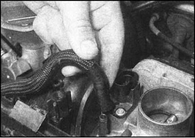
9. Disconnect the following hoses:
- a) Hose connecting inlet manifold to charcoal canister purge solenoid valve (on the mudguard of the left wheel arch);
- b) Vacuum hose of the brake booster from the inlet pipeline;
- c) Fuel supply and return hoses from the fuel line. Try to remember the direction of flow and the color coding of the hoses. Prepare to collect spilled fuel. Seal open ends of hoses and fittings immediately to prevent dirt from entering the fuel system and to minimize fuel wastage.
10. At the rear of the thermostat, release the wire clips securing the shroud to the water pump feed tube behind the engine block. Disconnect the remaining from the thermostat housing (try to remember the order in which they are connected).
11. Remove the accessory drive belt (see Section Removing, installing and adjusting the tension force of the auxiliary drive belt).
12. Remove the outer covers of the timing belt and the crankshaft pulley (see Sections Bringing the piston of the first cylinder to the top dead center position (TDC) end of compression stroke, Removal and installation of the timing belt and its covers). Remove the timing belt from the camshaft sprocket.
13. After removing the timing belt, the engine can be raised back to its original position, and the right machine support is connected.
14. In order to avoid accidental contact of the pistons with the valves during the removal of the head, the compilers of this Guide recommend turning the crankshaft back to a position a few degrees before TDC.
15. Remove the intake air heater plate from the top of the exhaust manifold.
... disconnect from a collector a reception pipe of system of release of the fulfilled gases. Remove the gasket.
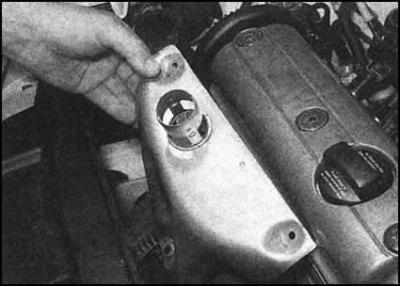
16. Turn out a bolt of fastening of a directing tube of the dipstick of measurement of level of impellent oil to a back part of a head of cylinders. If equipped, unbolt and remove the intake manifold support bracket.
17. Disconnect the throttle cable (see chapter Supply system).
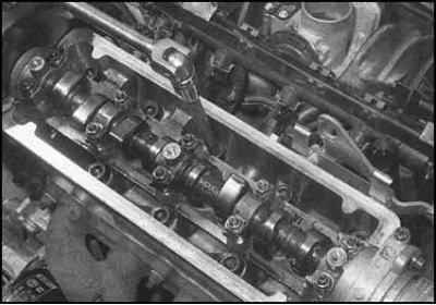
18. Remove the cylinder head cover (see Section Removal and installation of a cover of a head of cylinders).
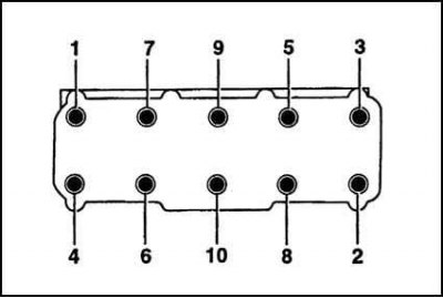
19. Acting in the order indicated in the illustration,...
...in several steps (half a turn per approach) loosen the head bolts enough to be able to turn them out by hand.
20. Make sure that no communication lines remain connected to the cylinder head. Remove the head from the cylinder block (if necessary, use the help of an assistant, especially if the head is removed assembled with pipeline and manifold).
21. Remove the gasket from the head mating surface of the block. Don't throw it away by saving it as a template.
22. If a major overhaul of the head is expected.
Separation from intake manifold head and exhaust manifold
23. The description of procedures of removal and installation of the inlet pipeline is given to Chapter Supply system.
24. In several stages, give the remaining fixing nuts (during assembly, the nuts must be replaced without fail) and remove the exhaust manifold with gaskets from the cylinder head.
25. Thoroughly clean the mating surfaces, install new gaskets, then install the exhaust manifold. Fit new fixing nuts and tighten them to the required torque.
Assembly preparation
1. Using a soft scraper, carefully clean the mating surfaces of the head and block. Remove all traces of old gasket material and carbon deposits from surfaces. Clean also the bottoms of the pistons. Try to keep debris out of water galleries and oil drains (carbon particles can tightly block the oil supply to the internal components of the engine) - seal all accessible holes with tape. The gaps between the walls of pistons and cylinders for the same purpose should be filled with grease, which can then be easily removed with a thin brush.
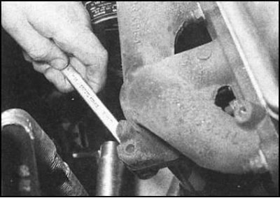
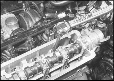
2. Check the mating surfaces of the block and cylinder head for scratches, scuff marks and other mechanical damage. Minor imperfections can be removed with a fine-toothed file. In case of more serious damage, you will have to resort to machining.
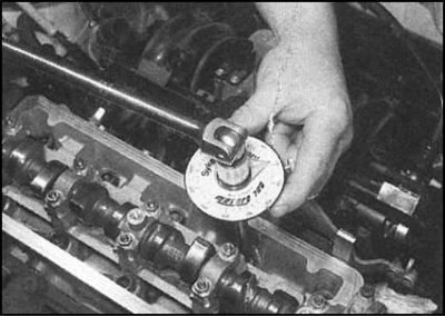
3. Evaluate the flatness of the mating surfaces using a special template (ribs of steel ruler) and a blade type probe.
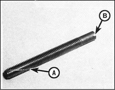
4. Check up a condition of bolts of fastening of a head, paying special attention to their carving part. Rinse the boots in solvent, then dry thoroughly. Defective bolts must be replaced. Measure the length of each of the mounting bolts to look for signs of stretching (this check cannot be considered unambiguous, since all the bolts can be stretched to the same length). The compilers of this Guide recommend replacing the head bolts, regardless of their condition.
5. Drive the bolt holes in the cylinder block with a suitable tap, clearing the threads and repairing the damaged turns.
Note. In the absence of a suitable tap at hand, the holes can be cleaned using a homemade device made from a long hairpin with sawn threads along the thread.
6. To avoid damage to pistons and valves, the compilers of this Guide recommend that before installing the head, take the crankshaft 90°back from the TDC position (if necessary, refer to the materials of the Section Description of the main components and mechanisms).
Assembly
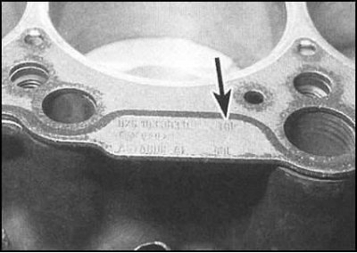
1. Make sure that the replacement gasket matches the size removed from the engine. Thoroughly wipe the mating surfaces of the cylinder head and cylinder block with a clean, dry rag, then lay a new gasket on the block, making sure that all the holes provided are aligned correctly. The gasket must be installed with the marking facing up. Screw long studs with a slot for a screwdriver sawn in the end part into a pair of bolt holes in the block. These studs will be used as guide pins when installing the head.
2. Make sure that the alignment marks of the camshaft gear and the inner timing chain cover are correctly aligned (see Section Bringing the piston of the first cylinder to the top dead center position (TDC) end of compression stroke). Try not to allow the shaft to rotate during the installation of the head.
3. With the help of an assistant, carefully slide the head assembly with tubing and manifold onto the guide studs. Before the final lowering of the head on the block, once again make sure that the gasket is correctly positioned.
4. Lightly lubricate the threads and undersurfaces of the mounting bolt heads with a high-quality high-temperature grease.
5. Insert each bolt carefully into its own hole and hand-tighten.
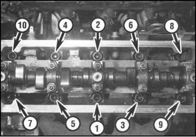
6. In order...
..tighten the bolts in several stages with the force of the first stage of tightening.
7. Moving in the same order, tighten the bolts to second stage torque.
8. Using a special goniometer or a template made of thick cardboard, tighten the bolts to the angle of the third stage of tightening.
9. Finally tighten the bolts to the fourth stage corner.
10. Reinstall the cylinder head cover (see Section Removal and installation of a cover of a head of cylinders).
11. If removed, reinstall the components of the ignition distributor (see chapter Engine electrical equipment).
12. Install the hose clamp on the supply pipe fitting on the thermostat housing.
13. Connect the throttle cable, if necessary, adjust it (see chapter Supply system).
14. Install the guide tube of the dipstick for measuring the level of impellent oil on the head. Tighten the mounting bolt.
15. Connect to a final collector a reception pipe of system of release of the fulfilled gases (see chapter Supply system). Install the intake air heater cover plate.
16. With the timing belt removed, bring the engine to TDC (see Section Bringing the piston of the first cylinder to the top dead center position (TDC) end of compression stroke).
17. Support the engine, disconnect the right support and slightly lower the power unit. Remove the outer covers of the timing belt and the crankshaft pulley (see Section Removal and installation of the timing belt and its covers).
18. The machine can now be lifted in and its right support can be connected (see Section Removal and installation of the timing belt and its covers).
19. Install the accessory drive belt and adjust its tension (see Section Removing, installing and adjusting the tension force of the auxiliary drive belt).
20. Further assembly is carried out in the reverse order of dismantling:
- a) Restore the original connection of all hoses and electrical wiring;
- b) Install the air cleaner assembly (see chapter Supply system);
- c) Fill the cooling system and check the engine oil level;
- d) Connect the negative wire to the battery.