



Assembly diagram of the cylinder head
Important: If installing a removable cylinder head, lubricate all contact areas between the hydraulic tappets, rocker arms and cam friction surfaces with oil before installing the cylinder head cover. The supplied plastic washers that protect the exposed valves can only be removed immediately before installing the cylinder head. Before starting assembly work, it is necessary to lubricate all bearing support surfaces and working surfaces with oil.
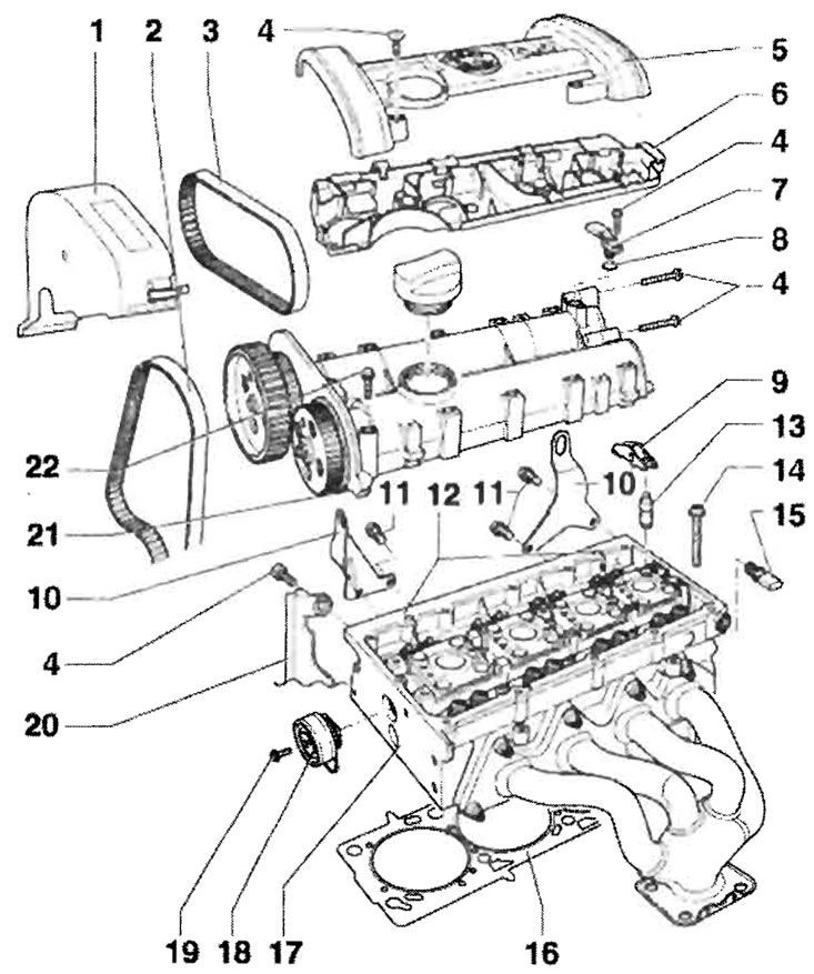
1 - Toothed belt guard - upper part; 2 - Before removing the main drive toothed belt, mark the direction of movement; 3 - Before removing the toothed belt of the connecting drive, mark the direction of movement; 4 - 10 Nm; 5 - Protective cap; 6 - Wire, screw onto the cylinder head cover with 8 Nm; 7 - Hall sensor "G40"; 8 - O-ring seal, replace; 9 - Rocker arm, check the ease of movement of the roller bearing, lubricate the friction surfaces with oil, during assembly install with a locking clamp on the hydraulic pusher; 10 - Eye; 11-20 Nm; 12 - Mounting pins; 13 - Hydraulic tappet, do not confuse with hydraulic valve clearance adjustment, lubricate the friction surface with oil, before proceeding with installation, check the axial clearance of the camshaft; 14 - Cylinder head mounting bolt, replace; 15 - Oil pressure drop switch-sensor with hydraulic drive 0.03-0.07 MPa -F1 -, 25 Nm, if the seal is broken, cut the sealing ring and replace; 16 - Cylinder head gasket, replace, metal gasket; 17 - Cylinder head, sealing surfaces with the cylinder head cover must be freed from oil and grease, after replacement, renew the entire filling volume of coolant; 18 - Tension roller of the coupling drive; 19 - 20 Nm; 20 - Rear toothed drive belt guard; 21 - Cylinder head cover, when installing, place it perpendicularly from above onto the spacer bolts and mounting pins; 22 - 10 Nm + turn an additional 1/4 turn (90°), replace, tighten from the inside out
Repair of the valve timing mechanism
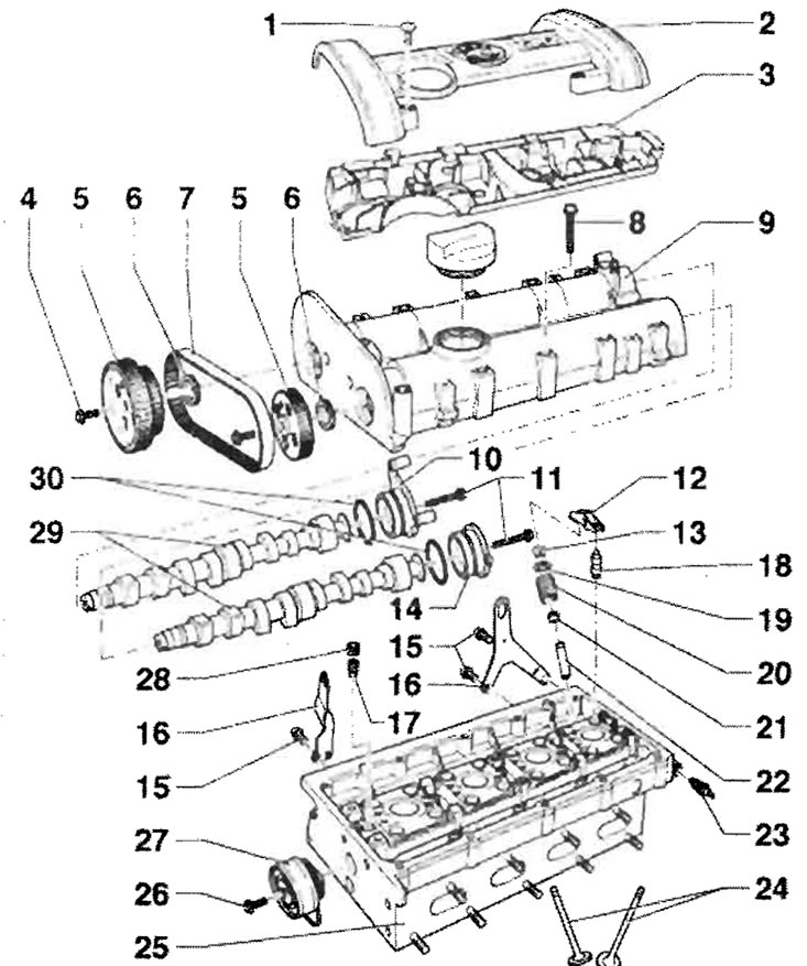
1 - 10 Nm; 2 - Protective cap; 3 - Wire; 4 - 20 Nm + turn an additional 1/4 turn (90°); 5 - Drive gear (pulley) of the camshaft; 6 - O-ring, replace only when the camshaft is installed, lightly lubricate the working edge of the O-ring with oil; 7 - Before removing the toothed belt of the connecting drive, mark the direction of movement; 8 - 10 Nm + turn an additional 1/4 turn (90°), replace, tighten from the inside out; 9 - Cylinder head cover, when installing, place it from above perpendicularly onto the spacer bolts and mounting pins; 10 - Lid; 11 - 10 Nm; 12 - Rocker arm, check the ease of movement of the roller bearing, lubricate the friction surface with oil, for assembly purposes, secure the locking clamp to the hydraulic tappet; 13 - Checks; 14 - Lid; 15 - 20 Nm; 16 - Eye; 17 - Check valve, 6 Nm, clean the threads and install with sealant, do not tighten too tightly, otherwise the valve may get stuck; 18 - Hydraulic tappet, do not overtighten with hydraulic valve clearance adjustment, lubricate the friction surface with oil; 19 - Valve spring plate; 20 - Valve spring; 22 - Valve guide bushing; 23 - Oil pressure drop switch-sensor with hydraulic drive 0.03 - 0.07 MPa "F1", 25 Nm, if the seal is broken, cut the sealing ring and replace; 24 - Valves, do not adjust, only grinding is allowed; 25 - Cylinder head; 26 - 20 Nm; 27 - Tension roller of the coupling drive; 28 - Screw plug, 45 Nm, install with sealant, must not be screwed in too deeply, maximum: starting recess below the mating surface of the cylinder head cover - 2 mm; 29 - Lubricate the camshafts with oil before installing them, and replace the sealing rings after installation; 30 - O-ring, replace, lubricate with oil before use
(Text taken from this website: www.SKODABOOK.ru)