
Brake system components with ABS
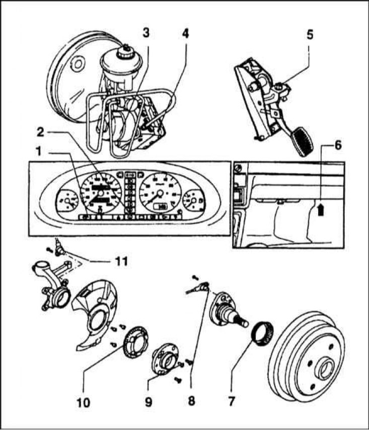
1 - ABS warning lamp; 2 - A control lamp of level of a brake liquid; 3 - ABS hydraulic pump; 4 - Hydraulic modulator; 5 - Sensor-switch of brake lights; 6 - Location of the diagnostic connector; 7 - Impulse disk (signal rotor) rear wheel sensor; 8 - Rear wheel speed sensor; 9 - Bolt; 10 - Impulse disk (signal rotor) front wheel sensor; 11 - Front wheel speed sensor
Functional diagram of the braking system with ABS
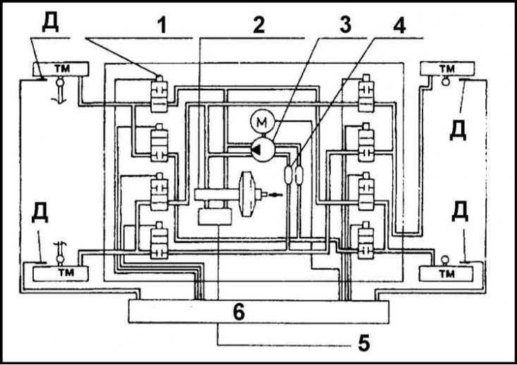
D - Wheel sensor; TM - Brake mechanism; 1 - Electrohydraulic valve; 2 - GTZ; 3 - Pump; 4 - Valves for diagonal separation of circuits; 5 - Brake fluid reservoir; 6-ECU
Location of the front wheel speed sensor
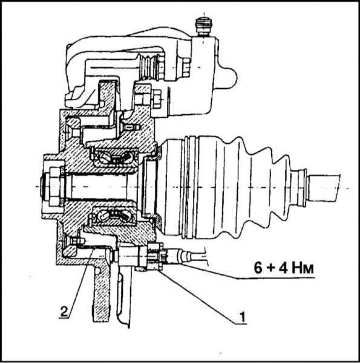
1 - Wheel sensor; 2 - Impulse disk (rotor)
Location of the rear wheel speed sensor
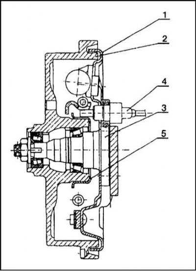
1 - Brake shield; 2 - Brake drum; 3 - Hub; 4 - Wheel sensor; 5 - Impulse disk (rotor)
Note. Cars are equipped with ABS manufactured by ITT Automotive Europe. The kit includes: amplifier 9'', GTZ tandem type (W 23.8 mm), hydraulic modulator and connecting lines. The thread for connecting the hydraulic lines of the right and left wheels on the modulator assembly is different - M12x1 and M10x1, respectively.
ABS is standard on some models and optional on others. The system includes a hydraulic modulator with an electronic control unit installed on it (ECU) and four wheel sensors. The modulator is equipped with hydraulic solenoid valves (two for each of the brake mechanisms [one intake and one exhaust]) and electric pump. The task of the system is to prevent premature blocking of the vehicle's wheels during heavy braking. This goal is achieved by instantaneous pressure modulations in the hydraulic circuits of the wheel brakes.
The operation of the modulator solenoid valves is controlled by the ECU, which continuously receives information about the speed of rotation of each of the vehicle's wheels from four wheel sensors. By analyzing the incoming signals, the ECU determines the current speed of the vehicle and uses it as a reference point in determining when each wheel starts to lock. Under normal conditions, the brake system functions as a conventional non-ABS equipped brake system.
At the moment of the beginning of the blocking of any of the wheels, the ECU issues a command to operate the corresponding exhaust solenoid valve (ov) hydraulic modulator. As a result, this brake (s) is isolated from the GTZ and the pressure in it ceases to rise.
If the wheel speed (wheels) continues to decrease, the control unit issues a command to open the intake solenoid valve (ov) and activates the electric pump, which pumps the brake fluid back into the GTZ, restoring freedom of rotation to the locked wheel (am). Once the wheel speed (wheels) rises to an acceptable value, the pump turns off, and the solenoid valve (s) restores the connection of the hydraulic circuit of the corresponding brake mechanism (ov) with GTS. The cycle can be repeated many times per second, allowing you to maintain control of the vehicle during hard braking, regardless of the condition of the road surface.
The operation of the solenoid valves and the return pump causes pulsations in the hydraulic circuit, so foot brake pedal jolts during ABS operation are normal and should not be a cause for concern.
The functioning of the ABS is entirely based on the electrical signals generated by the wheel sensors. In order to avoid false positives of the modulator, the ECU is equipped with a special control circuit that monitors all signals entering the unit. If a suspicious signal is received, or if signs of a decrease in the battery output voltage are detected, the corresponding control lamp lights up on the instrument panel, informing the driver about the ABS failure. At the same time, the braking system continues to function normally, providing adequate braking of the vehicle.
During the operation of the vehicle, monitor the tightness of the connections of the hydraulic path and the condition of the electrical wiring. ABS components do not require additional maintenance.
In the event of a malfunction of the ABS, the car should be driven to the service station of the company, where a complete diagnosis of the system using a special reader and appropriate repairs will be carried out.