
Note. The material in this Section applies only to non-ABS models.
Examination
1. On non-ABS models, the hydraulic circuit of each of the rear brakes is equipped with a pressure control valve, which helps to avoid premature locking of the rear wheels of the vehicle during heavy braking. Depending on the configuration of the model, either one valve-regulator that is sensitive to the degree of loading of the car, or two valves that are sensitive to changes in hydraulic pressure can be used.
2. Regulator valves sensitive to changes in pressure in the tract are screwed directly into the outlet fittings of the rear brakes of the GTZ. The design of the GTZ ensures the independent operation of two hydraulic circuits - primary and secondary, each of which acts on one front and one (diagonal) rear wheels. Regulator valves act as limiters, preventing the hydraulic pressure acting on the rear brakes from rising above a certain limit. With this scheme, the braking force developed by the front wheels is always greater than that developed by the rear.
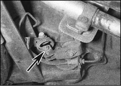
3. The only valve-regulator that is sensitive to the degree of loading of the car is installed on the bottom of the car, in its rear part and is connected to the rear suspension axle with a special spring. Based on the displacement of the bridge relative to the bottom, the valve determines the level of the weight load on the rear wheels and accordingly adjusts the maximum allowable hydraulic pressure developed in the rear brake circuits.
4. Checking the proper functioning of the regulator valves is carried out using special diagnostic equipment and for its implementation the car should be driven to a service station. Refurbishment of failed control valves is not possible, and therefore defective components must be replaced as an assembly.
Removing
Pressure sensitive control valves
Note. Before proceeding with the procedure, read the warning text at the beginning of Section System design, description of individual components and mechanisms.
1. To minimize hydraulic fluid loss, remove the GTZ reservoir cap, place plastic wrap underneath and screw tightly into place.
2. Thoroughly wipe the control valve to be removed and the surface of the GTZ around it.
3. Give a cap union nut, disconnect a brake tube, then turn out the valve regulator from the main cylinder. Remove and discard the old sealing washer and must be replaced during assembly. Seal the open ends of the tubing and fitting immediately to minimize hydraulic fluid loss and prevent dirt from entering the system. Wash off any spilled liquid immediately with plenty of cold water.
Load-sensing control valve
1. Chock the front wheels, then jack up the rear of the vehicle and place it on jack stands.
2. Mark the position of the valve spring bolt head in relation to the lever. Give a nut and remove a bolt of fastening of a spring to the valve. Remove washers.
3. Thoroughly wipe the fittings of the brake lines and the surfaces surrounding them, substitute a drain container under the fittings. To avoid confusion, mark the valve and the pipes connected to it.
4. Give union nuts and disconnect brake pipes from the valve. Seal open pipe ends and valve ports immediately to minimize hydraulic fluid loss and prevent dirt from entering the system. Wash off any spilled liquid immediately with plenty of cold water.
5. Remove the mounting screws and remove the valve assembly from the support bracket.
Installation
Pressure sensitive control valves
1. Clean the union threads on the GTZ and valve. Replace sealing washers. Screw the valve onto the fitting and tighten it firmly.
2. Connect the brake pipe to the valve by firmly tightening the union nut.
3. Remove the plastic film from under the GTZ reservoir cap and completely bleed the brake system (see Section Bleeding the hydraulic system).
Load-sensing control valve
1. Slide the valve assembly into place and secure it securely with screws.
2. Connect the brake lines to your fittings on the valve (check the markings made during dismantling) and firmly tighten the union nuts.
3. Install the valve spring bolt, making sure the washers are correctly positioned. Screw on the nut. Match the marks made when removing the bolt and tighten the nut to the required torque.
4. Remove the plastic film from under the cap of the GTZ reservoir and completely bleed the brake system (see Section Bleeding the hydraulic system). The compilers of this Guide recommend driving the car to a service station to check the proper functioning of the regulator valve.