



Contents: Progress of work ⬇ Disconnecting the quick-release…⬇ Removal the sealing ring (oil seal) ⬇ Installing the retaining ring ⬇ Quick coupling connection ⬇
Disconnecting quick-acting couplings of the coolant circulation system pipelines.
Important: After any disconnection of the quick release coupling, the O-ring, retaining insert and retaining ring must be replaced. The following text describes how to disconnect the low pressure side quick couplings. The procedure for disconnecting the high-pressure side quick-acting couplings is the same.
Progress of work
The coolant circulation system is completely drained.
Disconnecting the quick-release coupling
Remove the right headlight and sound insulation. Remove the coolant line from clamp "3". Remove dust cap "1" from coupling "2" to the extent that it is possible to install a release tool.

Important: The distance "a" of the low-pressure side protective hose from the quick-release coupling must be at least 20 mm, otherwise it will not be possible to install the release tool. If necessary, after removing the dust cap, carefully cut the protective hose in the axial direction and fold it forward.

Install the release tool "2" on the coolant line "1" and on the coupling body "3" so that the areas of the release tool "arrow A" correspond to the areas on the coupling "arrow B".

Place the release tool "1", despite the noticeable resistance, until it stops in the direction of the "arrow" on the coupling body "2".
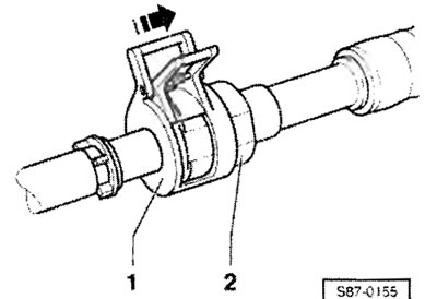
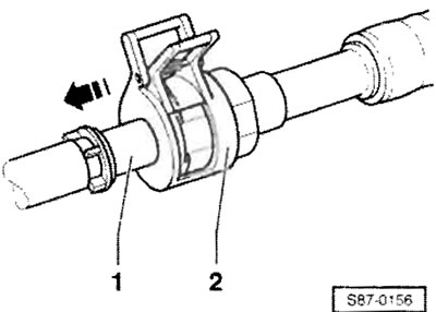
Press the release tool "2" against the stop on the coolant line "1". Pull the coolant line "1" together with the release tool "2" in the direction of the "arrow" out of the coupling housing. After loosening the locking device for release "2", remove it.
Removal the sealing ring (oil seal)
Remove retaining ring "1" using suitable pliers.
Remove the locking insert "1" from the coupling housing "3".

To do this, press the 2 protrusions of "arrow A" into the holes of "arrow B" to such an extent that the locking insert can be removed. Remove O-ring seal "2".

Installing the retaining ring
After lubricating the new O-ring "1" with coolant oil, insert it into the clutch housing "2" until it stops.
(Information presented on the website SKODABOOK.ru)

Important: Take into account the different O-ring sizes for the high-pressure side and the low-pressure side.
Install the new locking insert "1" into the coupling housing "2". The locking pins "arrow A" must engage in the locked position in the holes "arrow B".

Install retaining ring "1" using suitable pliers.
Quick coupling connection
Press the coolant line "1" into the coupling housing "3" until it clicks into place.

The locking insert tabs should visibly protrude from the holes in the clutch housing. Install dust cap "2" until it stops against the clutch housing. Press the coolant line back into the clamp on the longitudinal beam.
