



Important: After replacing the brake pad friction linings, you should press the brake pedal firmly several times with the vehicle stationary to ensure that the friction linings are in their working position. Before you begin removing the disc brake caliper or disconnecting the brake hose from the brake caliper, you must secure the brake pedal with a device (spacer bar) to hold the brake pedal. To suck out brake fluid from the hydraulic brake reservoir, use a vessel to remove air that comes into contact only with the brake fluid. Brake fluid that has already been used cannot be reused. Tightening torque of wheel mounting bolts: 120 Nm.
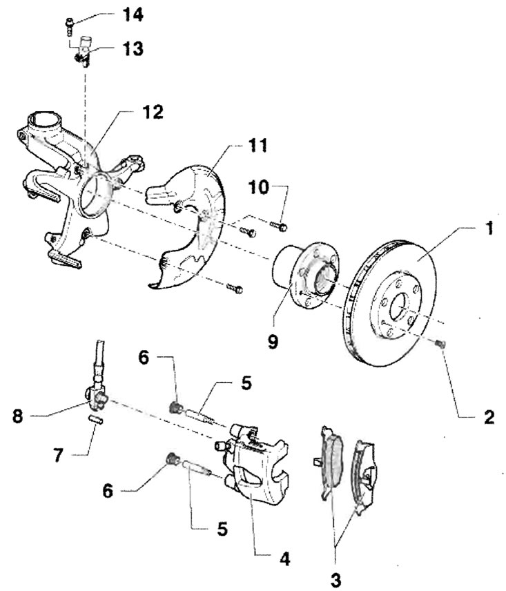
Assembly diagram of the front wheel brake mechanism FS-III
- 1 - Brake disc, thickness: 22 mm, wear limit: 19 mm, replace on both sides of the bridge, eg. rust remover, otherwise the wheels will be damaged
- 2 - Screw, 4 Nm
- 3 - Friction linings (segments), with wear indication, when wear is appropriate (border: 2...3 mm) the indicator light on the instrument panel is on, Thickness: 19.6 mm (incl. support plate), wear limit: 2.0 mm without backing plate
- 4 - Disc wheel brake support
Removal
Remove the friction linings. Install the brake pedal holding device. Unscrew the brake hose from the disc brake caliper.
Installation
Install friction linings. Screw the brake hose onto the disc brake caliper. Remove the brake pedal holding device. Bleed the brake system.
- 5 - Guide pin, 28 Nm
- 6 - Cap
- 7 - Elastic bushing
- 8 - Brake hose with nipple, hollow screw and sealing rings, do not disassemble, replace only one piece, as a set, tightening torque: 35 Nm
- 9 - Wheel hub with wheel hub bearing
- 10 - Screw, 10 Nm
- 11 - Protective sheet
- 12 - Wheel hub bearing cap
- 13 - ABS Speed Sensor
- 14 - Hexagon socket head cap screw, 8 Nm, for ABS speed sensor
Data Copied from the portal SKODABOOK.RU