



Contents: For engines with letter designations…⬇ For engines with the letter…⬇ Continued for all vehicles ⬇ Installation ⬇
With the ignition off, disconnect the wire connecting the battery terminal to the ground (body) of the vehicle. Remove the upper engine cover. Remove the upper boost air pipe "1" with connecting hose "2" "arrows".
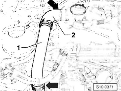
Remove the air duct from the front wall and air filter. Remove the air filter with the air intake sleeve. Remove the charge air pipe with the connecting hose to the turbocharger. Disconnect the glow plug connector from the glow plugs. Unscrew the turbocharger oil supply line (also on the oil filter holder and from the mount).
For engines with letter designations BNM, BNV
Remove the EGR cooler from the exhaust manifold and intake manifold. Unscrew the inlet pipe from the inlet gas line and set it aside with the attached hoses. Disconnect the front section of the exhaust pipe with the catalytic converter from the exhaust manifold. Remove the lower engine cover. Remove the charge air connecting hose between the turbocharger and the lower charge air pipe.
For engines with the letter designation BMS
Important: Remove only the mounting bracket and disconnect the front section of the exhaust manifold with the particulate filter from the turbocharger.
Remove the front exhaust manifold with the particulate filter from the turbocharger. Remove the lower engine cover.
(Article reprinted from the website: SkodaBook)
Continued for all vehicles
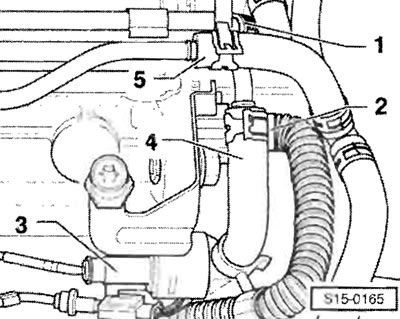
Disconnect the intake hoses from the turbocharger. Remove the turbocharger oil drain line. Drain the coolant. Using a hand vacuum pump and a vessel to remove air, drain the fuel from the return fuel line of the tandem pump. Disconnect fuel hoses "1" and "4". Disconnect coolant hose "5". Remove central plug connector "2" for the pump-injector units. Disconnect plug connector "3" on the fuel temperature sensor "G81".
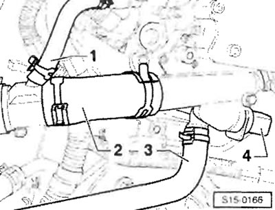
After disconnecting coolant hose "1" from the tee, disconnect coolant hoses "2" and "3" from the connecting pipe. Disconnect plug connector "4" from coolant temperature sensor "G62".
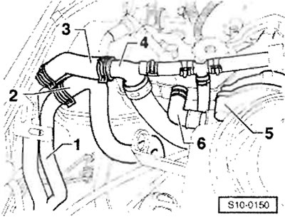
Disconnect coolant hose "3" from fitting "4". Disconnect intake hose "6" from dual pump "5". Disconnect the coolant hose leading to the EGR cooler from the connecting pipe.
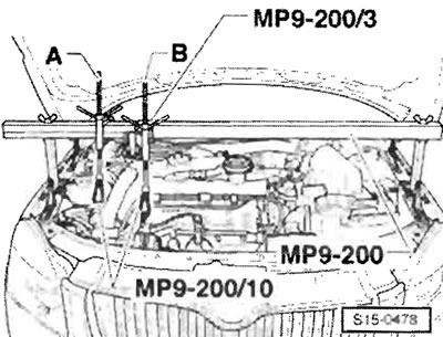
After installing the "MP 9-200 (10-222A)" suspension device with the lead screws inserted as shown in the figure, secure the engine with lead screw "B." Carefully lift the engine with lead screw "B." Remove the toothed drive belt. Remove the drive gear and camshaft hub. Remove the timing belt tensioner roller.
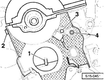
After unscrewing screw "3", remove the Hall sensor "G40" from the cylinder head. Unscrew screws "2" and "4".
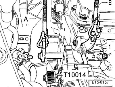
Screw the "T10014" holder into the threaded hole on the water pump section of the cylinder block. Tightening torque: 20 Nm. Grip and carefully lift the engine with lead screw "A" and thereby release lead screw "B". Remove lead screw "B". Remove the cylinder head cover.
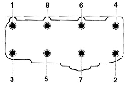
Observe the sequence when loosening the cylinder head bolts. Lift the cylinder head and remove it to the side around the toothed drive belt protective cover.
Installation
Important: Cylinder head bolts must always be replaced. When repairing, it is necessary to clean the mating surfaces of the cylinder block and cylinder head from gasket residues using a chemical agent to eliminate the seal. When handling the gasket remover, wear protective gloves and goggles! Remove the new cylinder head gasket from its packaging only immediately prior to installation. The new gasket must be handled with extra care. Damage to the silicone layer and the knurled area leads to loss of sealing.
Before installing the cylinder head, rotate the crankshaft to the TDC mark. Rotate the crankshaft counterclockwise until all pistons are at approximately the same TDC level. Install the cylinder head gasket. After installing the cylinder head, tighten all 8 cylinder head mounting bolts by hand and tighten the cylinder head mounting bolts in four stages in the sequence shown as follows.
1. Pre-tightening with a spanner with a calibrated tightening torque.
- Stage I = 40 Nm
- Stage II = 60 Nm
2. Turn additionally with a rigid wrench.
- Stage III = 1/4 turn (90°)
- Stage IV = 1/4 turn (90°)
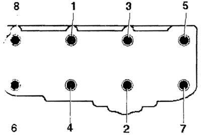
Important: There is no need to tighten the cylinder head mounting bolts after repair.
After securing the cylinder head, rotate the camshaft so that the cams of cylinder 1 point evenly upward. Before installing the timing belt, rotate the crankshaft to TDC in the direction of engine rotation. After installing the cylinder head, prime the tandem pump and the cylinder head with fuel using a hand vacuum pump and a bleeder. Further installation is carried out in the opposite sequence of actions than extraction. Carry out a test run, count the fault memory. Check the oil level.