



Caution: The tandem pump must not be disassembled, as this may cause the vacuum portion of the pump to not function properly. The consequence would be failure of the brake booster.
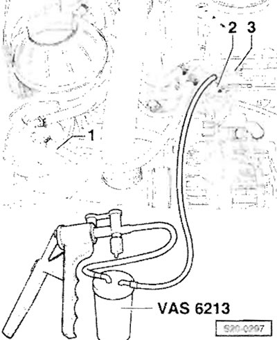
Remove the supply hose "1" (with white markings) from the fuel filter and drain hose "2" (with blue markings) from the fuel line pipe "3". Connect the hand vacuum pump to the pipe "3" of the return fuel line on the head. Use a hand vacuum pump to create a vacuum until fuel begins to flow out of the return fuel line. Make sure that no fuel is sucked into the hand vacuum pump.
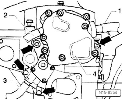
Disconnect the intake hose "1" for the brake booster from the tandem pump type "4". Disconnect the supply hose "2" (with white markings) from a tandem pump type "4". Unscrew the mounting screws "arrows". Remove the tandem pump type "4" from the cylinder head. After moving the double pump "4" upwards, disconnect it from the return fuel line hose "3" (with blue markings) and remove the tandem pump type "4".
Installation
Installation is carried out in the reverse order of actions; the following instructions must be followed.
Important: Ensure correct installation from the tandem pump coupling to the camshaft. It is always absolutely necessary to replace the twin pump seal.
Connect the return fuel line hose "3" (with blue markings) to the connecting pipe for the return fuel line of a dual tandem pump. After installing the tandem pump, tighten the M8 support screw to a torque of 20 Nm. Tighten the M6 support screws to a torque of 8 Nm. Connect the supply hose "2" (with white markings) to the connecting element of the connecting hose and the intake hose "1" from the brake booster - to the dual tandem pump "4". Connect the supply hose "1" (with white markings) to the fuel filter. Connect a hand vacuum pump (e.g. "VAS 6213") to tube "3" of the return fuel line. Use a hand vacuum pump to create a vacuum until fuel begins to flow out of pipe "3" of the return fuel line.
Important: Make sure that no fuel is sucked into the hand vacuum pump.
Connect the fuel return hose "2" (with blue markings) to the fuel line pipe "3".
Accelerator Pedal Module - Assembly Diagram
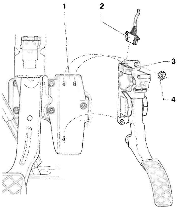
1 - Bearing housing (support bracket); 2 - Plug connector, six-pin, black; 3 - Accelerator pedal module, with accelerator pedal position sensor "G79" and accelerator pedal position sensor 2 "3185", before proceeding with the removal of the sensor, it is necessary to remove the lower part under the instrument panel on the driver's side, not adjustable; 4 - 9 Nm
[Information published on the website www.SkodaBook.ru]