



Contents: For engines with letter designations…⬇ For all cars ⬇ Installation ⬇ Removal and installation a…⬇ Installation ⬇ Removal and installation a…⬇ Wiring diagram of intake hoses for…⬇ Removal and installation of charge…⬇
Remove the right front wheel arch (fender) liner. Remove the front bumper.
For engines with letter designations BNM, BNV
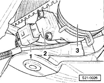
Disconnect plug connector "1" from boost pressure sensor "G71" with intake air temperature sensor "G72" ("2").
For all cars
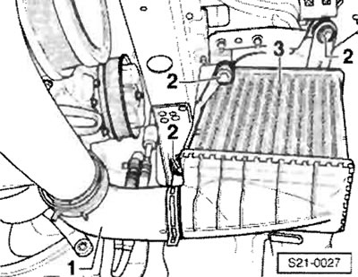
Disconnect connecting hose "3" from the charge air cooler pipe. Remove the air duct from the charge air cooler.
Disconnect the connecting hose "1" from the charge air cooler "3". After unscrewing the screws "2", remove the charge air cooler "3".
Installation
Installation is carried out in a similar manner, in the reverse order of actions.
Removal and installation a turbocharger for engines with the letter designations BNM, BNV
Caution: If mechanical damage to the turbocharger has occurred, or the centrifugal compressor wheel has become unusable, simply replacing the turbocharger is not enough. To prevent further damage to the engine, the following work must be performed. Check the air filter housing, filter element, hoses and charge air pipes for contamination. Check all air ducts and the charge air cooler for foreign bodies. If contamination or foreign bodies are detected in the boost pressure system, it is necessary to thoroughly clean all air ducts and, if necessary, also replace the charge air cooler.
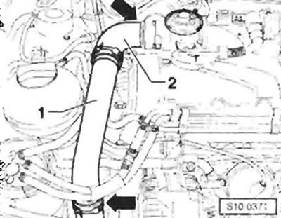
Remove the upper engine cover. Remove the upper boost air pipe "1" with connecting hose "2" "arrows". Remove the crankcase ventilation pipe. Remove the air intake sleeve from the rear charge air pipe and air filter. Remove the air duct from the front wall and air filter. Remove the air filter. Remove the intake manifold flap motor "V157". Remove the rear charge air pipe with the connecting hose to the turbocharger. Remove the protective sheet.
Clear the turbocharger oil supply line. Remove the EGR cooler from the exhaust manifold and intake manifold. Remove the intake hose from the EGR valve. Remove the intake manifold with the mechanical EGR valve. Unscrew the front section of the exhaust manifold. Remove the lower engine cover. Unscrew the protective cover of the propeller shaft from the cylinder block. Remove the lower intake manifold with the turbocharger connecting hose. Disconnect the intake hoses from the turbocharger. Unscrew the oil drain line from the turbocharger. After removing the exhaust manifold, pull it out together with the turbocharger in an upward direction.
Installation
Installation is carried out in a similar manner, in the reverse order of actions. In this case, the following instructions must be observed.
Important: Tightening torques. Self-locking nuts must be replaced with new ones. After installing the turbocharger, the engine should be left running for approx. 1 min at idle speed to allow oil to enter the turbocharger.
Removal and installation a turbocharger with installed parts for an engine with the letter designation BMS
Information taken from this resource: SKODABOOK.ru
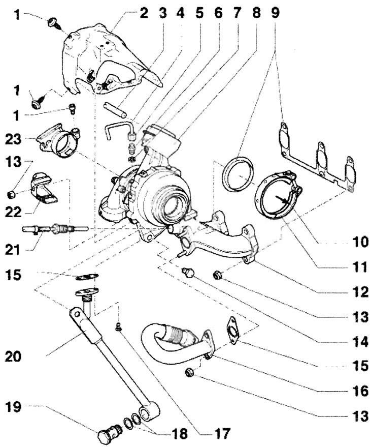
1 - 9 Nm; 2 - Heat-protective casing; 3 - Intake hose; 4 - Inlet lubrication line, from the oil filter holder, before installing the inlet lubrication line, you should check its capacity, before screwing on the inlet lubrication line, you should fill the connecting pipe with engine oil; 5 - Union nut, 22 Nm; 6 - Connecting pipe, 30 Nm, replace; 7 - O-ring, replace; 8 - Vacuum regulator, boost pressure control, integral part of the turbocharger, cannot be replaced separately; 9 - Seal, replace, observe the assembly position; 10 - To the particulate filter; 11 - Fastening clamp, 7 Nm, replace, for turbocharger and particulate filter; 12 - Turbocharger with exhaust manifold, can be replaced as one part only; 13 - 25 Nm, replace; 14 - 25 Nm; 15 - Seal, replace; 16 - Connecting pipe, exhaust gas recirculation system; 17 - 15 Nm; 18 - O-ring seal, replace; 19 - Hollow screw, 60 Nm; 20 - Support, for turbocharger, with oil drain line; 21 - Temperature sensor before turbocharger "G235", 45 Nm, before installation, lubricate the threads with paste for connections subject to thermal stress "G 052 112 A3"; 22 - Heat-protective casing; 23 - Connecting pipe for the air intake hose from the air filter
Wiring diagram of intake hoses for engines with the letter designation BMS
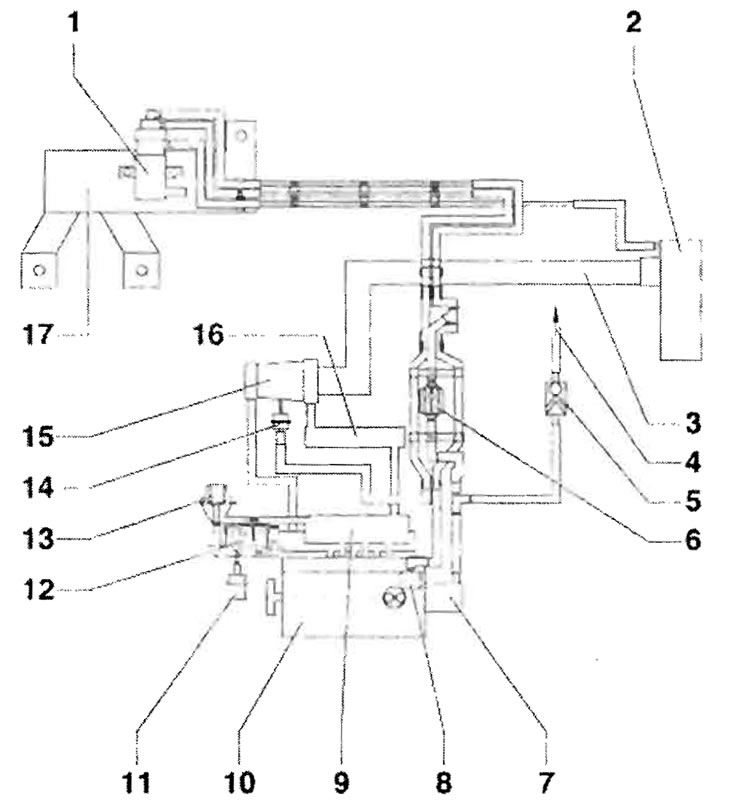
1 - Solenoid valve for limiting boost pressure "N75"; 2 - Air filter; 3 - Inlet hose; 4 - To the brake booster; 5 - Check valve; 6 - Check valve, white connector - to the boost pressure limiting solenoid valve and to the vacuum receiver; 7 - Tandem type double pump; 8 - Vacuum receiver; 9 - Intake manifold; 10 - Cylinder head; 11 - Vacuum regulator, for bypass valve; 12 - Radiator, exhaust gas recirculation system; 13 - EGR valve "N18" with EGR potentiometer "G212" and EGR regulator "V338"; 14 - Vacuum regulator, boost pressure control, integral part of the turbocharger, cannot be replaced separately; 15 - Turbocharger; 16 - Charge air cooler; 17 - Holder
Removal and installation of charge air cooling system components for engines with the letter designation BMS
Important: All hose connections are secured with clamps. The supercharging system must be sealed. Boost pressure hoses and boost air pipes, as well as their connections, must be free of oil and grease before reassembly.
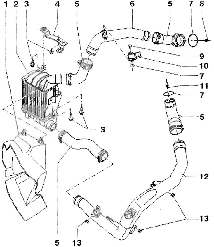
1 - Air duct; 2 - charge air intercooler; 3 - 8 Nm; 4 - Holder; 5 - Connecting hose; 6 - Charge air intake pipe, from charge air cooler to intake manifold; 7 - O-ring seal, replace if damaged; 8 - To the inlet pipe; 9 - 3 Nm; 10 - Intake air pressure sensor "G31" with intake air temperature sensor "G42"; 11 - From the turbocharger; 12 - Charge air intake pipe, from turbocharger to charge air cooler; 13 - 8 Nm