



Important: Depending on the design condition, there is a plastic tube located on the ATF cooler inlet part that must be reinstalled during installation.
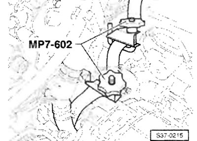
After closing the ATF cooler hoses with "MP7-602 (3094)" tube clamps, remove them from the ATF cooler.
Remove the ATF cooler "1" from the "arrow A" gearbox.
Installation
Installation is carried out in the reverse order of actions. In this case, the following instructions must be observed. Replace O-ring seals of ATF oil cooler.
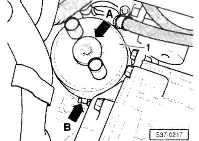
The disc spring must be installed so that it fits against the washer and so that the convex side of the disc spring faces upward. When installing the ATF cooler, insert the tab "arrow B" into the recess in the gearbox housing.
| Design detail | Nm |
| ATF fluid cooler on the transmission | 36 |
Install the ATF cooler hoses according to the markings on the ATF cooler. Check the coolant level in the cooling system. Subsequently, the ATF fluid level should be checked and, if necessary, ATF fluid should be added.
ATF Cooler - Parts Overview
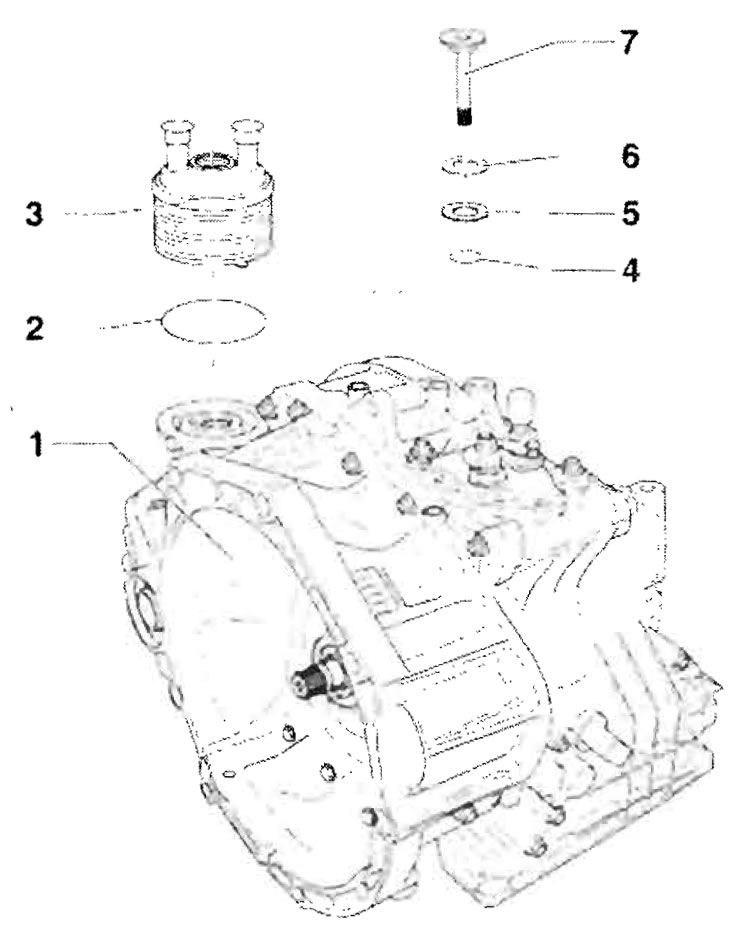
1 - Gearbox housing; 2 - O-ring seal, replace; 3 - Heat exchanger for cooling ATF fluid; 4 - O-ring seal, replace; 5 - Washer; 6 - Disc spring. Assembly position: Should be adjacent to washer pos. 5, the outward convex side of the disc spring should be facing upwards; 7-36 Nm
Oil pan, oil strainer, valve body, and internal wiring harnesses - parts overview
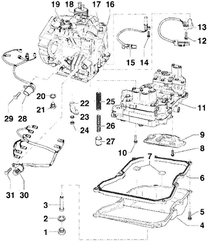
1 - Threaded plug for checking the ATF fluid level M10 - 27 Nm, replace the sealing ring - pos. 2, check the ATF fluid level and, if necessary, top up; 2 - O-ring, replace; 3 - Bypass pipe -2 Nm, screw into the oil pan with a 5 mm Allen key; 4 - Oil pan; 5 - 7 Nm, 8 pieces for securing the oil pan with oil pan seal to the gearbox housing; 6 - Seal; 7 - Magnet, 2 pieces in the recesses of the oil pan, before proceeding with installation, clean; 8 - 11 Nm, 3 pieces for securing the ATF fluid network filter to the valve box; 9 - ATF fluid mesh filter; 10 - Screw M6, 12 pieces of different lengths for fixing the valve box on the gearbox, replace, select the correct part; 11 - Valve box; 12 - 6 Nm; 13 - Gearbox input shaft speed sensor "G182", with wire and two-pin plug connector; 14 - 7 Nm; 15 - Gearbox output shaft speed sensor "G195", with wire and two-pin plug connector; 16 - Gearbox housing; 17 - Device for removing air from ATF fluid; 18 - Heat exchanger for cooling ATF fluid; 19 - Multifunctional switch "F125", checked by the automatic control system; 20 - O-ring, replace; 21 - Threaded plug for draining the ATF fluid M18 - 40 Nm; 22 - Lever, inner shaft of preselector lever on valve box; 23 - Washer 10 Nm, observe position for assembly; 25 - Large spring; 26 - Small spring; 27 - Shock absorber piston; 28 - Wiring harness with eight-pin plug connector and integrated oil temperature sensor in the "G93" gearbox, with O-ring seal on the plug connector; replace the O-ring seal; 29 - 6 Nm; 30 - wiring harness with 14-pin connector, with O-ring seal on the connector; replace the O-ring seal; 31 - 6 Nm